6 dynamic loading, 7 capacitive loading, Dynamic loading – SSI America ERP2U User Manual
Page 22: Capacitive loading, Table 20: voltage regulation limits, Table 21: optional +5v regulation limits, Table 22: transient load requirements
SSI
ERP2U Power Supply Design Guide, V2.31
- 22 -
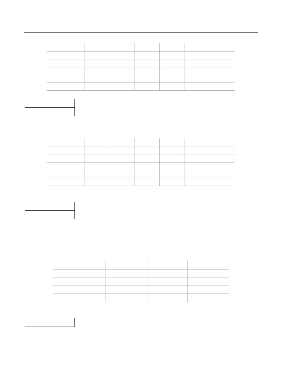
Table 19: Voltage Regulation Limits
Parameter MIN NOM MAX Units Tolerance
+3.3
V
+3.14 +3.30 +3.47 V
rms
+/-5%
+5
V
+4.75 +5.00 +5.25 V
rms
+/-5%
+12V1,2,3,4 +11.40 +12.00 +12.60 V
rms
+/-5%
-12
V
-10.80 -12.20 -13.20 V
rms
+/-10%
+5
VSB
+4.75 +5.00 +5.25 V
rms
+/-5%
STATUS
Optional
Some system applications may require tighter regulation limits on the outputs. The optional regulation limits are
shown below.
Table 20: Optional +5V Regulation Limits
Parameter MIN NOM MAX Units Tolerance
+3.3V
+3.20 +3.30 +3.47 V
rms
+5/-3%
+5
V
+4.85 +5.00 +5.25 V
rms
+5/-3%
+12V1,2,3,4 +11.64 +12.00 +12.60 V
rms
+5/-3%
-12V -11.40
-12.00 -13.08 V
rms
+9/-5%
+5
VSB
+4.85 +5.00 +5.25 V
rms
+5/-3%
6.6 Dynamic
Loading
STATUS
Required
The output voltages shall remain within the limits specified in Error! Reference source not found. for the step
loading and within the limits specified in Table 22 for the capacitive loading specified in below. The load transient
repetition rate shall be tested between 50 Hz and 5 kHz at duty cycles ranging from 10%-90%. The load transient
repetition rate is only a test specification. The
Δ step load may occur anywhere within the MIN load to the MAX
load range.
Table 21: Transient Load Requirements
Output
Δ Step Load Size Load Slew Rate Capacitive Load
+3.3 V
30% of max load
0.5 A/
μs
1000
μF
+5 V
30% of max load
0.5 A/
μs
1000
μF
12V1+12V2+12V3+12V4
65% of max load
0.5 A/
μs
2200
μF
+5 VSB
25% of max load
0.5 A/
μs
1
μF
6.7 Capacitive
Loading
STATUS