Led interface module - 4xlm, Optional modules 2. installation – System Sensor PDRP-1002 Series User Manual
Page 27
Optional Modules
2. Installation
PDRP-1002 Instruction Manual PN 51135:B0 04/06/01
27
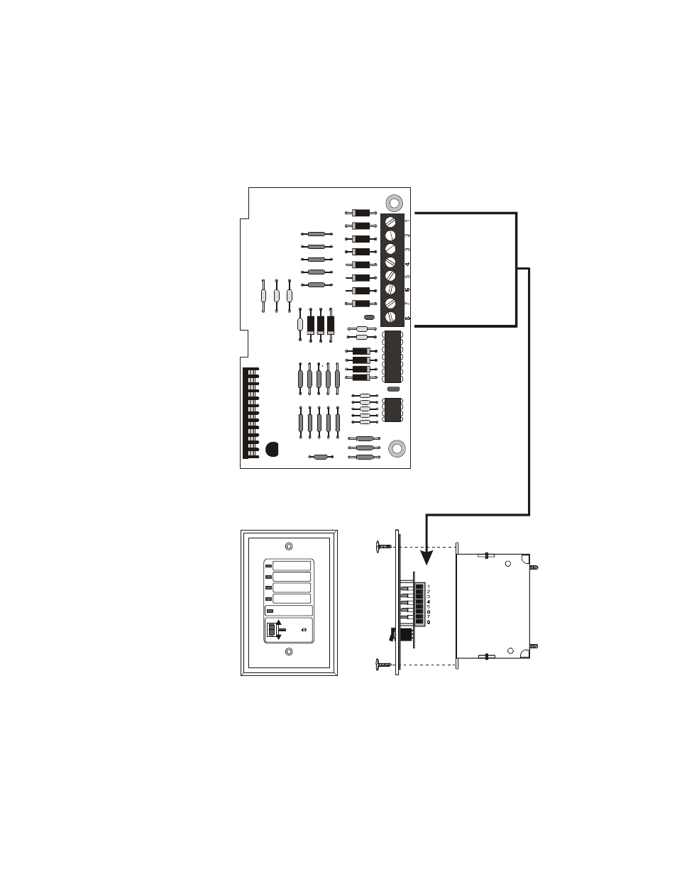
LED Interface Module - 4XLM
Connect the terminals on TB1 of the LED Interface Module to the corresponding terminals of the RZA-
4X Remote Annunciator.
Make wiring connections with system power off.
Maximum wire impedance is 50 ohm per wiring connection.
The wiring of this module must follow the requirements as specified under "Power-limited Wiring
Requirements" on page 17.
Figure 18 Connection of 4XLM to RZA-4X
SYST EM TR O U BLE
R E-SO UN D
TO N E
SIL EN C E
FIR E ALA R M AN N UN CIATO R
TB
1
J 2
Connect to corresponding
terminals of the RZA-4X
Remote Annunciator.
Front View
Side View
M
S
44-
-4
xlm
fco
nn.cdr
Single-gang
Box
+24V
Out #1
Out #2
Out #3
Out #4
Sysyem Trouble
Sound
Resound