Zone relay module - 4xzm – System Sensor PDRP-1002 Series User Manual
Page 26
2. Installation
Optional Modules
26
PDRP-1002 Instruction Manual PN 51135:B0 04/06/01
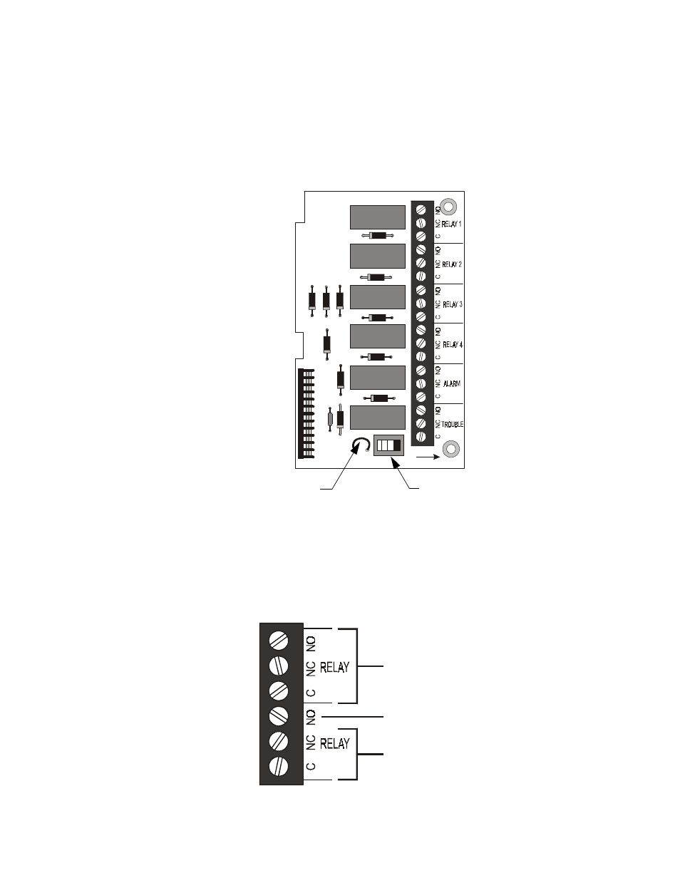
Zone Relay Module - 4XZM
Relay #1 through #4 on this module have specific functions based on the configuration of DIP switches
#1 and #2 on the control panel. See “Zone Relay Module Configuration” on page 30 for a more detailed
explaination of the conditions that will activate each relay under the different DIP switch setings.
For non-latching (silenceable) relay operation, cut the jumper “LATCH”. If this jumper is left intact, the
relays will latch upon activation. To disconnect relays entirely, slide the disable switch to the right.
Note: If any dry contacts are to be used as nonpower-limited circuits, write this on the Protected Premises Unit label,
located on the door of the control panel.
Figure 16 Wiring the Zone Relay Module
The wiring of this module must follow the requirements specified under "Power-limited Wiring
Requirements" on page 17.
• If this module is used to drive both nonpower-limited and power-limited circuits, skip one set of
dry contacts to maintain the required separation between circuit types.
• If this module is used to drive both nonpower-limited and power-limited relays that are next to each
other, refer to the figure below which shows the one allowable arrangement.
Figure 17 Mixing Power-Limited and Nonpower-Limited Circuits
T B1
LAT C H
D IS ABL E
J2
Disable Switch
“Latch” Jumper
4X
Z
M
F
.cdr
Power-Limited
Circuit
Nonpower-Limited
Circuit
MS
44-
-4xzm
f1.cdr
No Connection