Optional modules, Overview, Installation - upper position – System Sensor PDRP-1002 Series User Manual
Page 23: Optional modules 2. installation
Optional Modules
2. Installation
PDRP-1002 Instruction Manual PN 51135:B0 04/06/01
23
Optional Modules
Overview
The control panel has two module connectors - J5 (upper position) and J8 (lower position). Three modules
are available for the panel and they can be used in any combination, including duplicate modules. The
corresponding option jumper must be cut before installation of an optional module, to enable module
supervision.
• The 4XTM Transmitter and 4XZM Zone Relay Modules can be installed in either position.
• The 4XLM Interface Module must be installed in the lower position only.
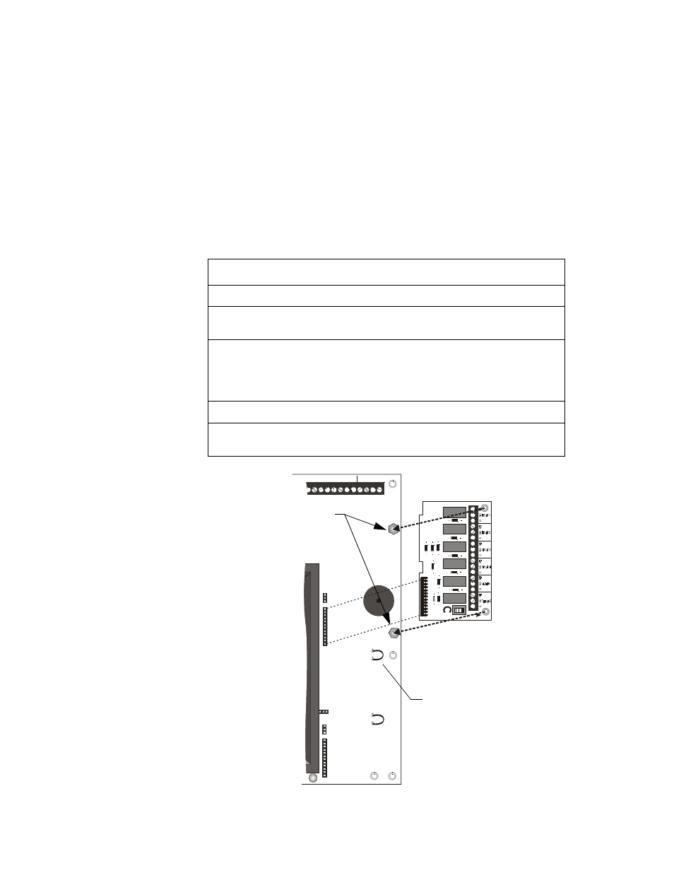
Installation - Upper Position
To install either the 4XTM or 4XZM module in the upper position follow these instructions:
Figure 13 Module Installation - Upper Position
Step
Action
1
Cut jumper ‘OPT1’ on main circuit board.
2
Insert the two stand-offs into the holes located on the right-side edge of the
main board. Secure with nuts and tighten securely.
3
Align the pins of J5 (and J4) connectors on the main board with the
holes on the underside of the J2 (and J1) connector on the optional
board. Carefully press down on the optional board until the pins are
through the connectors and it rests on the stand-offs.
4
Secure optional board to stand-offs with screws. Tighten securely.
5
Affix the terminal identification label (provided with the module) on the
back surface of the backbox, aligning it with the terminals on the module.
T B 4
J4
J5
J7
J8
O PT 1
O PT 2
J10
B –
IN #2
B+ A+ A– B–
IN #3
B+ A+ A– B–
IN #4
B+ A+ A– B–
TB 1
LAT CH
DISAB LE
J2
MS
44-
in
stmo
d1.cdr
OPT1 - Cut prior to
installation of module
Install Stand-offs here