Reinstallation of circuit board, Installation cabinet mounting 14 – System Sensor PDRP-1002 Series User Manual
Page 14
2. Installation
Cabinet Mounting
14
PDRP-1002 Instruction Manual PN 51135:B0 04/06/01
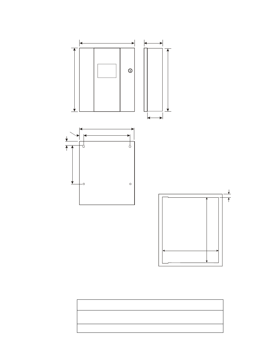
The figure below shows the exterior dimensions and mounting hole locations for the cabinet backbox and
dimensions of the optional trim ring:
Figure 2 Cabinet Mounting Dimensions
Reinstallation of Circuit Board
Reinstall the printed circuit board as follows:
Step
Action
1
Position circuit board over stand-offs on backbox rail and secure with four
(4) phillips screws. Tighten securely.
2
Connect transformer wires to J1 connector on circuit board.
1 4.62 5 ”
(3 7.15 cm )
1 6.12 5 ”
(4 0.96 cm )
5 .3 75 ”
(1 3.65 cm )
1 6.00 ”
(4 0.64 cm )
4 .7 5”
(1 2.07 cm )
1 4.50 ”
(3 6.83 cm )
1 2.50 ”
(3 1.75 cm )
9 .5 0”
(2 4.13 cm )
1 .0 0”
(2 .5 4cm )
1 .0 0”
(2 .5 4cm )
1.5”
(3.81cm )
16.125”
(40.96cm )
14.625”
(37.15cm )
M
S
4
4
-cab
di
m.cd
r
M
S
4
4
-tr
imri
ng
.c
dr