Horizontally vented, category iii - figure 15, Standard combustion – Sterling TUBULAR GAS FIRED DIRECT SPARK PROPELLER UNIT HEATERS GG-30 User Manual
Page 21
21
HORIZONTALLY VENTED, CATEGORY III - Figure 15
Observe the following precautions
when venting the unit:
1. Use fl ue pipe of the same size
as the fl ue connection(s) on the
gas unit heater, 4" (102mm). All
heaters must be vented with a
single or double wall pipe listed
for category III positive pressure
vent systems.
Type B double wall pipe can be
used with limitations as shown in
Figure 15B. As illustrated, a
single 5 foot (1.52m) section of
Type B vent pipe with a draft
hood connector may be used
between the appliance vent
connection and the vent terminal.
Use Metalbestos Type B gas
vent with a Metalbestos 4RV-DH
draft hood connector, or, an
Amerivent Type B gas vent with
an Amerivent 4EDC draft hood
connector.
2. Each unit must have an
individual vent pipe and vent
terminal. Unit MUST NOT be
connected to other vent systems
or to a chimney.
3. Category
III units are limited to
a maximum of 40 feet (12.19m)
equivalent length of vent pipe.
Equivalent length is the total
length of straight sections PLUS
5 feet (1.5m) for each 90 degree
elbow and 2.5 feet (.75m) for
each 45 degree elbow.
4. If using a single section of Type
B vent pipe, seal the annular
space between the inner and
outer sections of the draft hood
connector with a high temper-
ature silicone sealant. Use
General Electric RTV-108, Dow-
Corning RTV-732, or equivalent
silicone sealant with a temper-
ature rating of 500 deg. F. See
Figure 15C. Attach the draft
hood connector to the appliance
vent connection with screws
(3 minimum) and seal the joint
with silicone sealant. Install a
Type B vent thimble in the wall.
Inser t the vent pipe through
the thimble and attach it to the
adapter on the appliance. Seal
the joint with silicone sealant or
two wraps of aluminum foil tape.
Install a vent cap on the outlet
pipe and secure with screws (3
minimum).
5. An Amerivent Americap or
Metalbestos vent cap must be
supplied by the customer for
each power vented unit. The vent
pipe diameter must be 4 inches
(102mm).
6. Through the wall venting for
these appliances shall not
terminate over public walkways,
or over an area where the
condensate or vapor could
create a nuisance, hazard, or
could be detrimental to the
operation of regulators, relief
valves, or other equipment, see
Figures 15A, 16 and 18.
7. The vent terminal must be at
least 3 feet (1m) above grade,
or in snow areas, at least 3 feet
above the snow line to prevent
blockage by snow.
8. The vent terminal must be at
least 12 inches (305mm) from
the exterior of the wall that
it passes through to prevent
degradation of the building
materials by fl ue gasses.
9. M a i n t a i n 1 - i n c h ( 2 5 . 4 m m )
clearance between the vent
pipe and combustible materials.
10. Seal all vent pipe joints and
seams to prevent leakage. Use
General Electric RTV-108, Dow-
Corning RTV-732, or equivalent
silicone sealant with a temper-
ature rating of 500 deg.F, or 3M
#425 aluminum foil tape (or
equivalent). The vent system
must be installed to prevent
collection of condensate. Pitch
horizontal pipes downward 1/4
inch per foot (21mm per meter)
toward the outlet for condensate
drainage. Install a tee with a
condensate drain at the low point
of the pipe (see Figure 15A). As
an alternate, a 3/8 inch diameter
hole may be drilled at the low
point of the pipe for condensate
drainage.
11. Horizontal portions of the venting
system shall be supported at
minimum intervals of 4 feet
(1.2m) to prevent sagging (in
Canada, support at 3 foot (1m)
minimum intervals).
12. Avoid running vent pipe through
unheated spaces. When this
cannot be avoided, insulate the
pipe to prevent condensation
of moisture on the walls of the
pipe.
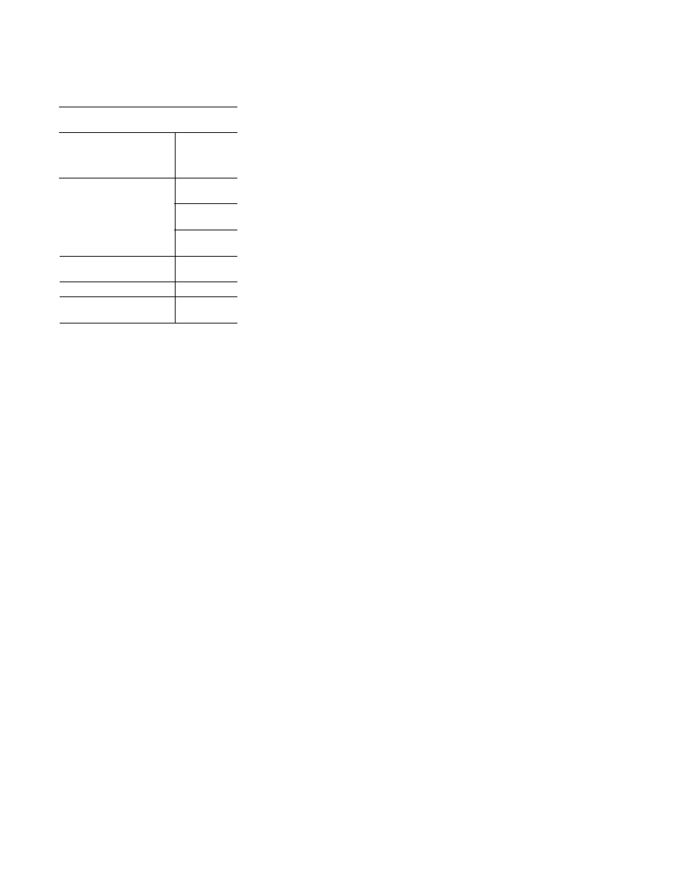
Door, window or
any gravity air inlet
Forced air inlet within 10 ft.
Adjoining building or parapet
Adjacent public walkways
Minimum
Clearances for
Termination
Locations
Structure
4 feet
below
4 feet
horizontally
1 foot
above
3 feet
above
6 feet
7 feet
above grade
Vent Systems
Termination Clearance Requirements
STANDARD COMBUSTION
- TUBULAR GAS FIRED DIRECT SPARK PROPELLER UNIT HEATERS GG-60 TUBULAR GAS FIRED DIRECT SPARK PROPELLER UNIT HEATERS GG-105 TUBULAR GAS FIRED DIRECT SPARK PROPELLER UNIT HEATERS GG-120 TUBULAR GAS FIRED DIRECT SPARK PROPELLER UNIT HEATERS GG-45 TUBULAR GAS FIRED DIRECT SPARK PROPELLER UNIT HEATERS GG-75 TUBULAR GAS FIRED DIRECT SPARK PROPELLER UNIT HEATERS GG-90