Electrical connections (continued) – Sterling TUBULAR GAS FIRED DIRECT SPARK PROPELLER UNIT HEATERS GG-30 User Manual
Page 15
15
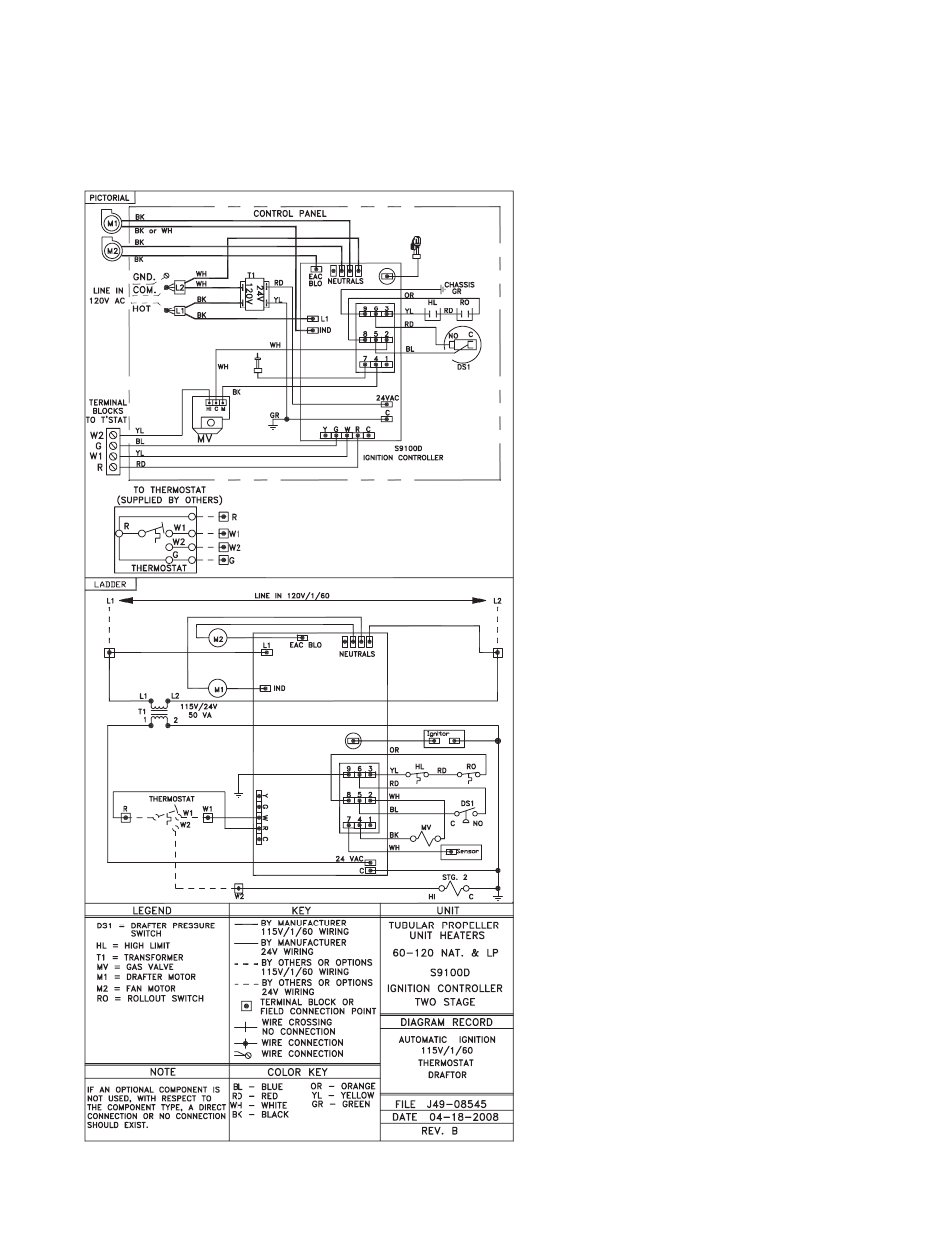
Figure 11C - Tubular Propeller Units 30-120 with Natural and Propane (LP) Gas
with Optional Two Stage Gas Control and Honeywell Control Board
ELECTRICAL CONNECTIONS (continued)
NOTICE: See Figures 7, 8, 9, 10B, 10C, 11B
and 11C for connecting the thermostat to the
unit heater. If using a standard low voltage
thermostat with a sub-base switch for fan
control, connect the G terminal of the thermostat
to the G terminal of the unit heater.
This manual is related to the following products:
- TUBULAR GAS FIRED DIRECT SPARK PROPELLER UNIT HEATERS GG-60 TUBULAR GAS FIRED DIRECT SPARK PROPELLER UNIT HEATERS GG-105 TUBULAR GAS FIRED DIRECT SPARK PROPELLER UNIT HEATERS GG-120 TUBULAR GAS FIRED DIRECT SPARK PROPELLER UNIT HEATERS GG-45 TUBULAR GAS FIRED DIRECT SPARK PROPELLER UNIT HEATERS GG-75 TUBULAR GAS FIRED DIRECT SPARK PROPELLER UNIT HEATERS GG-90