Schumacher Automatic /Maintainer SE-1-12S User Manual
Page 2
2
TIVE (RED) ring terminal from the battery charger to the POSITIVE (POS,
P, +) ungrounded post of the battery. Connect the NEGATIVE (BLACK) ring
terminal to the vehicle chassis or engine block away from the battery. Do not
connect the ring terminal to the carburetor, fuel lines, or sheet-metal body
parts. Connect to a heavy gauge metal part of the frame or engine block.
For positive-grounded vehicle : You should disconnect both battery cables
6.6
from the battery before connecting the charger cables. The output leads of
the charger are terminated with 3/8” dia. ring terminals. Remove the bolt
from the battery post connector, insert the bolt through the ring terminal then
place the bolt back in the battery connector and tighten. Connect the NEGA-
TIVE (BLACK) ring terminals from the battery charger to the NEGATIVE
(NEG, N, –) ungrounded post of the battery. Connect the POSITIVE (RED)
ring terminals to the vehicle chassis or engine block away from the battery.
Do not connect the ring terminals to the carburetor, fuel lines, or sheet-metal
body parts. Connect to a heavy gauge metal part of the frame or engine
block.
When disconnecting the charger, disconnect the AC cord, remove the ring
6.7
terminal from the vehicle chassis, and then remove the ring terminal from
the battery terminal.
FOLLOW THESE STEPS WHEN BATTERY IS OUTSIDE
7.
VEHICLE.
A SPARK NEAR THE BATTERY MAY CAUSE A BATTERY EXPLOSION. TO
REDUCE THE RISK OF A SPARK NEAR THE BATTERY:
Check the polarity of the battery posts. The POSITIVE (POS, P, +) battery
7.1
post usually has a larger diameter than the NEGATIVE (NEG, N, –) post.
Attach at least a 24-inch-long 6-gauge (AWG) insulated battery cable to the
7.2
NEGATIVE (NEG, N, –) battery post.
Connect the POSITIVE (RED) charger ring terminal to the POSITIVE (POS,
7.3
P, +) post of the battery.
Position yourself and the free end of the cable you previously attached to
7.4
the NEGATIVE (NEG, N, -) battery post as far away from the battery as pos-
sible – then connect the NEGATIVE (BLACK) charger ring terminal to the
free end of the cable using a nut and bolt through both ring terminals.
Do not face the battery when making the final connection.
7.5
When disconnecting the charger, always do so in the reverse order of the
7.6
connecting procedure and break the first connection while as far away from
the battery as practical.
A marine (boat) battery must be removed and charged on shore. To charge
7.7
it onboard requires equipment specially designed for marine use.
BATTERY CHARGING - AC CONNECTIONS
8.
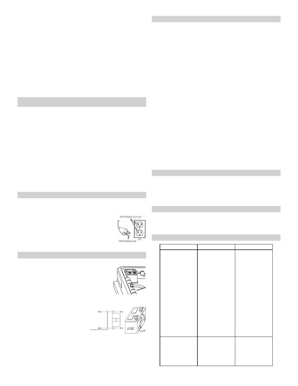
This battery charger is for use on a nominal 120-volt circuit and has a
8.1
grounded plug that looks like the plug illustrated. The charger must be
grounded to reduce the risk of electric shock. The plug must be plugged into
an outlet that is properly installed and grounded in ac-
cordance with all local codes and ordinances. The plug
pins must fit the receptacle (outlet). Do not use with an
ungrounded system.
DANGER – Never alter AC cord or plug provided – if
it does not fit the outlet, have proper grounded outlet
installed by a qualified electrician. Improper connection
can result in a risk of an electric shock or electrocution.
NOTE: The use of an adapter plug is not recommended.
MOUNTING INSTRUCTIONS
9.
Mounting the charger to the fender well: The SE-1-12S charger can be
mounted directly to the fender well of your vehicle as
shown. If using the nuts and bolts provided, drill two
holes between 3/16” and 1/4” in diameter. (For alignment
of holes use the charger as a template.) If the backside of
the mounting surface is hard to reach, you may consider
using two 1/2” long sheet metal screws (not included)
instead of the nuts and bolts provided.
Mounting the charger alongside the battery: The SE-
1-12S can also be mounted alongside your vehicle’s battery using the bracket
provided. If possible, mount the charger to the side of the battery away from
the engine and fan blades. Mount the bracket to the charger as
shown using the nuts and bolts provided.
Loosen the battery retaining hardware
enough that you can insert the bracket
between the bottom of the battery and the
battery mounting tray as shown. Position
the charger so that it will not rub against
the battery or any other part of the vehicle, and then tighten the
battery retaining hardware.
CAUTION: Do not drill or puncture the battery.
Electrical Installation – The output leads of the charger are terminated with 3/8”
dia. ring lugs. Route and secure the AC cord and the output wiring away from
the gas line, carburetor or other hot, sharp or moving and pinch parts to avoid
damage to the insulation. Secure the AC cord using a cable tie or equivalent. If
you have difficulty connecting the output leads, consult your local auto supply
store, they may assist you in finding a connecting device for your application.
OPERATING INSTRUCTIONS
10.
Charging
This charger is intended for use with 12 volt battery systems only. The charger
contains an electronic control circuit which safeguards against overcharging the
battery.
1. Connect the battery and AC power following the precautions listed in sec-
tions 6, 7 and 8.
2. The POWER ON (green) LED will light when the AC cord is properly con-
nected. When the battery is charged the CHARGED (red) LED will light
The charger then automatically switches between charge mode and maintain
mode as necessary. The CHARGED (red) LED will cycle on when the battery
is at full charge and off when the voltage drops below a preset level and the
charger goes into charge mode. This cycle will continue, and the CHARGED
(red) LED will stay on for longer periods of time as the battery becomes more
fully charged.
Charging Tips
Read this entire manual before using your battery charger. The following tips
serve only as a guide for specific situations.
Your charger has been designed NOT to spark if the ring terminals on the
•
leads accidentally touch one another, or if the leads are connected in reverse.
The battery must measure at least 1 volt to start the charging of the battery.
•
The POWER ON (green) LED will be on even if the charging is not taking
place. You can verify charging by measuring the battery voltage and noting an
increase in volts.
This charger is ideally suited for maintaining the battery charge level for the
•
following applications:
Storage of a battery during non-seasonal use.
ɶ
For vehicles seldom used or placed in storage.
ɶ
For improved battery performance during cold weather.
ɶ
For large automotive or marine batteries which are deeply discharged, it is
•
recommended to recharge it first with a larger charger (such as a 10 amp)
then use the SE-1-12S to maintain the charge level of the battery.
MAINTENANCE INSTRUCTIONS
11.
Before performing maintenance, unplug and disconnect battery charger (see
11.1
sections 6.7 and 7.6).
After use, unplug charger and use a dry cloth to wipe all battery corrosion
11.2
and other dirt or oil from terminals, cords, and the charger case.
Servicing does not require opening unit, as there are no user-serviceable
11.3
parts.
STORAGE INSTRUCTIONS
12.
Store charger unplugged. Cord will still conduct electricity until it is un-
12.1
plugged from outlet.
Store inside, in a dry, cool place.
12.2
Do not store ring terminals on or around metal or clipped together.
12.3
TROUBLESHOOTING
13.
PROBLEM
POSSIBLE CAUSE
SOLUTION
The charger is making
an audible clicking
sound.
This battery charger is
equipped with a self-
resetting circuit breaker.
This device protects the
charger from temporary
overloads. In the
event of an overload,
the breaker will trip
open and after a short
cooling off period will
reset automatically.
This process is known
as cycling and can
be recognized by an
audible clicking sound.
Battery is defective.
Shorted battery cables
or ring terminals.
Severely discharged
battery, but otherwise it
is a good battery.
Reverse connections at
battery.
Have the battery
checked.
Circuit breaker cycles
when current draw is
too high. Check for
shorted cables or ring
terminals and replace if
necessary.
The battery may not
want to accept a charge
due to a run-down
state. Allow charging to
continue until battery
has a chance to recover
sufficiently to take a
charge. If more than 20
minutes, stop charging
and have the battery
checked.
Shut the charger off
and correct the lead
connections.
Charger makes a loud
buzz or hum.
Transformer laminations
vibrate (buzz).
Shorted Diode
Assembly or Output
Rectifier Assembly
(hum).
No problem, this is a
normal condition.
Have charger
checked by a qualified
technician.