Chapter 7 configuration options, 1 switching hub configuration options, 1 power switching polarity – SMSC USB2524 User Manual
Page 20: 2 vbus detect, 3 port assignment configuration, Chapter 7, Configuration options, Switching hub configuration options 7.1.1, Power switching polarity, Vbus detect
USB MultiSwitch
TM
Hub
Datasheet
Revision 1.91 (08-22-07)
20
SMSC USB2524
DATASHEET
Chapter 7 Configuration Options
7.1
Switching Hub Configuration Options
The SMSC Hub supports a large number of features (some are mutually exclusive), and must be
configured in order to correctly function when attached to a USB host controller. There are three
principal ways to configure the hub: SMBus, EEPROM, or by internal default settings (with or without
pin strapping option over-rides). In all cases, the configuration method will be determined by the
CFG_SEL2, CFG_SEL1 and CFG_SEL0 pins immediately after RESET_N negation.
7.1.1
Power Switching Polarity
The selection of active state “polarity” for the PRTPWR pins is made by a strapping option only (the
PRTPWR_POL pin).
7.1.2
VBus Detect
According to Section 7.2.1 of the USB 2.0 Specification, a downstream port can never provide power
to its D+ or D- pull-up resistors unless the upstream port’s VBUS is in the asserted (powered) state.
The VBUS_DET pin on the Hub monitors the state of the upstream VBUS signal and will not pull-up
the D+ resistor if VBUS is not active. If VBUS goes from an active to an inactive state (Not Powered),
Hub will remove power from the D+ pull-up resistor within 10 seconds.
7.1.3
Port Assignment Configuration:
The order of precedence for control of ownership of each port is as follows:
1. CFG_SEL0 and CFG_SEL1.
2. PRT_ASSIGN_CFG register
3. PRT_ASSIGN_MODE register
4. PRT_LCK register
5. The applicable PORT_ASSIGN_INTxx or PORT_ASSIGN_xx register (based on the settings
above).
Note: The PRT_LCK register will primarily be used when in SMBus mode, but is available for use in
EEPROM Configuration, When the EEPROM port assignment values are loaded, the
PRT_LCK will be temporarily suspended, then after the configuration is loaded, the PRT_LCK
function will be enabled.
7.1.4
Internal Register Set (Common to EEPROM and SMBus)
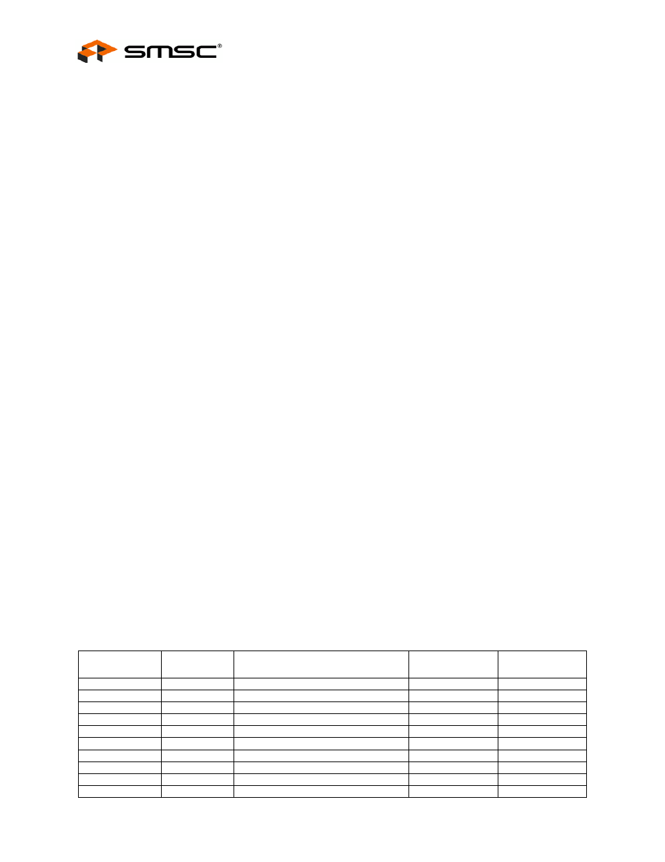
Table 7.1 Internal EEPROM & SMBus Register Memory Map
REG ADDR
R/W
REGISTER NAME
ABBR
DEFAULT
ROM
00h
R/W
VID LSB
VIDL
24h
01h
R/W
VID MSB
VIDM
04h
02h
R/W
PID LSB
PIDL
24h
03h
R/W
PID MSB
PIDM
25h
04h
R/W
DID LSB
DIDL
00h
05h
R/W
DID MSB
DIDM
00h
06h
R/W
Config Data Byte 1
CFG1
9Bh
07h
R/W
Config Data Byte 2
CFG2
10h
08h
R/W
Config Data Byte 3
CFG3
00h
09h
R/W
Non-Removable Devices
NRD
00h