Chapter 4 switching hub pin descriptions, Table 4.1 switching hub pin descriptions, Chapter 4 – SMSC USB2524 User Manual
Page 12: Switching hub pin descriptions, Datasheet
USB MultiSwitch
TM
Hub
Datasheet
Revision 1.91 (08-22-07)
12
SMSC USB2524
DATASHEET
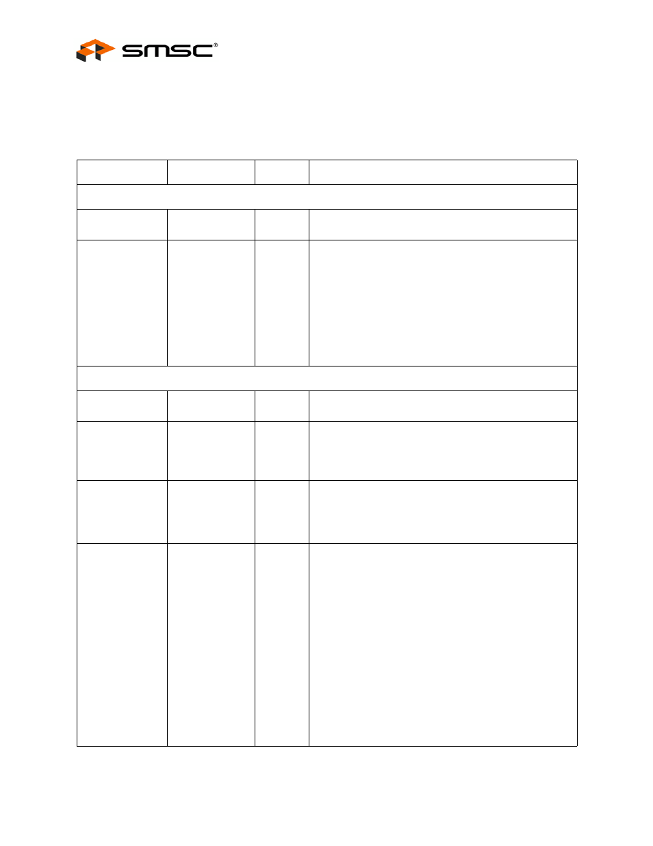
Chapter 4 Switching Hub Pin Descriptions
Table 4.1 Switching Hub Pin Descriptions
NAME
SYMBOL
TYPE
FUNCTION
UPSTREAM USB 2.0 INTERFACE
USB Bus Data
USBUP_DP[2:1]
USBUP_DM[2:1]
IO-U
These pins connect to the upstream USB bus data signals.
Detect Upstream
VBUS Power
VBUS_DET[2:1]
I/O
Detects state of Upstream VBUS power. The SMSC Hub
monitors VBUS_DET to determine when to assert the
internal D+ pull-up resistor (signalling a connect event).
When designing a detachable hub, this pin must be
connected to the VBUS power pin of the USB port that is
upstream of the hub. (Use of a weak pull-down resistor is
recommended.)
For self-powered applications with a permanently attached
host, this pin must be pulled-up to either 3.3V or 5.0V
(typically VDD33).
4-PORT USB 2.0 HUB INTERFACE
High-Speed USB
Data
USBDN_DP[4:1]
USBDN_DM[4:1]
IO-U
These pins connect to the downstream USB peripheral
devices attached to the Hub’s ports.
USB Power
Enable
PRTPWR[4:1]
O
Enables power to USB peripheral devices (downstream).
The active signal level of the PRTPWR[4] pin is determined
by the Power Polarity Strapping function of the
PRTPWR_POL pin.
Port 4:3 Green
LED
&
Port Disable
strapping option 0
LED_A[4:3]_N/
PRT_DIS[1:0]
I/O12
Green indicator LED for ports 4 and 3. Will be active low
when LED support is enabled via EEPROM or SMBus. See
PRT_DIS1 function description if the hub is configured by
the internal default configuration.
Port Disable
strapping option 1
PRT_DIS1
I/O12
If the hub is configured by the internal default configuration,
PRT_DIS[1:0] will be sampled at RESET_N negation to
determine if ports [4:2] will be permanently disabled. Also,
the active state of LED_A3_N will be determined as follows:
PRT_DIS[1:0] = '00', All ports are enabled,
LED_A4_N is active high,
LED_A3_N is active high.
PRT_DIS[1:0] = '01', Port 4 is disabled,
LED_A4_N is active high,
LED_A3_N is active low.
PRT_DIS[1:0] = '10', Ports 4 & 3 are disabled,
LED_A4_N is active low,
LED_A3_N is active high.
PRT_DIS[1:0] = '11', Ports 4, 3 & 2 are disabled,
LED_A4_N is active low,
LED_A3_N is active low.