8 led indicators, Table 3.1 led status indicators, 9 jumper settings – SMSC EVB-EMC2101 User Manual
Page 9: 1 device power, Table 3.2 device power, 2 fan control, Table 3.3 fan driver configuration
EVB-EMC2101 User Manual
SMSC EMC2101
Revision 1.5 (12-13-06)
9
3.8
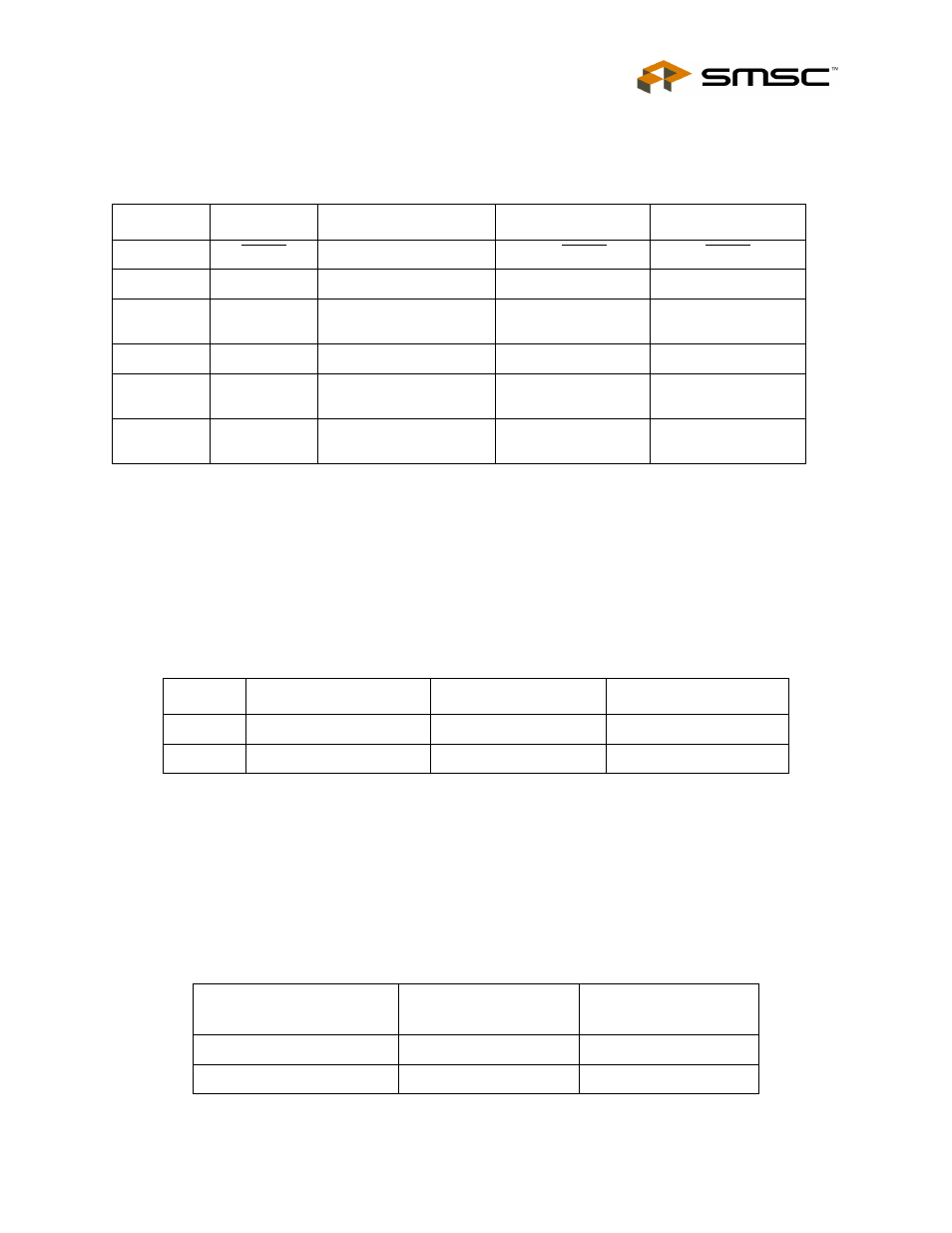
LED Indicators
LEDs indicate the status of the following signals (
).
3.9
Jumper Settings
This EVB has many jumper configurations to evaluate all of the features of the EMC2101.
3.9.1
Device Power
To enable one of the 2 devices on the EVB, use jumpers J2 and J3. When a device is selected, the
appropriate LED will light as shown in
below summarizes the options. Note: only
one device may be active at a time as both devices have the same SMBus address.
3.9.2
Fan Control
To adjust the fan control circuit one 3-way jumper is used. The two settings are DAC mode and PWM
mode. The default setting is PWM which requires the fan to be connected to FAN CONN. 1 and the
JP8 shorted from pin 1-2.
If the linear DAC mode is desired, several things need configured. First, JP8 must be shorted from pin
2-3 and the fan must be connected to FAN CONN. 2. Then, the device must be configured for linear
operation via the ChipMan software. Consult the datasheet for these settings.
.
Table 3.1 LED Status Indicators
LED
SIGNAL
OFF
GREEN
RED
LED1
ALERT
+3.3V power OFF
No ALERT
ALERT
LED2
+3.3V
+3.3V power OFF
+3.3V power ON
NA
LED3
Bridge Activity
NO Activity on
USB/SMBus Bridge
Activity on
USB/SMBus Bridge
NA
LED4
USB Activity
NO Activity on USB port
Activity on USB port
NA
LED5
EMC2101
Power
U10 power OFF
U10 power ON
NA
LED6
EMC2101-R
Power
U11 power OFF
U11 power ON
NA
Table 3.2 Device Power
JUMPER
NAME
POSITION 1-2
POSITION 2-3
J2
EMC2101 POWER
U10 power ON
U10 power OFF
J3
EMC2101-R POWER
U11 power ON
U11 power OFF
Table 3.3 Fan Driver Configuration
FAN DRIVER
CONFIGURATION
JP8
FAN CONNECTOR
PWM
Position 1-2
P9
DAC
Position 2-3
P5