Power supply interface and on/off control – Sierra Wireless MP215 User Manual
Page 16
MP215 Mobile Modem
Installation, Configuration, and User’s Guide
Sierra Wireless Inc.
05/11/99
3-2
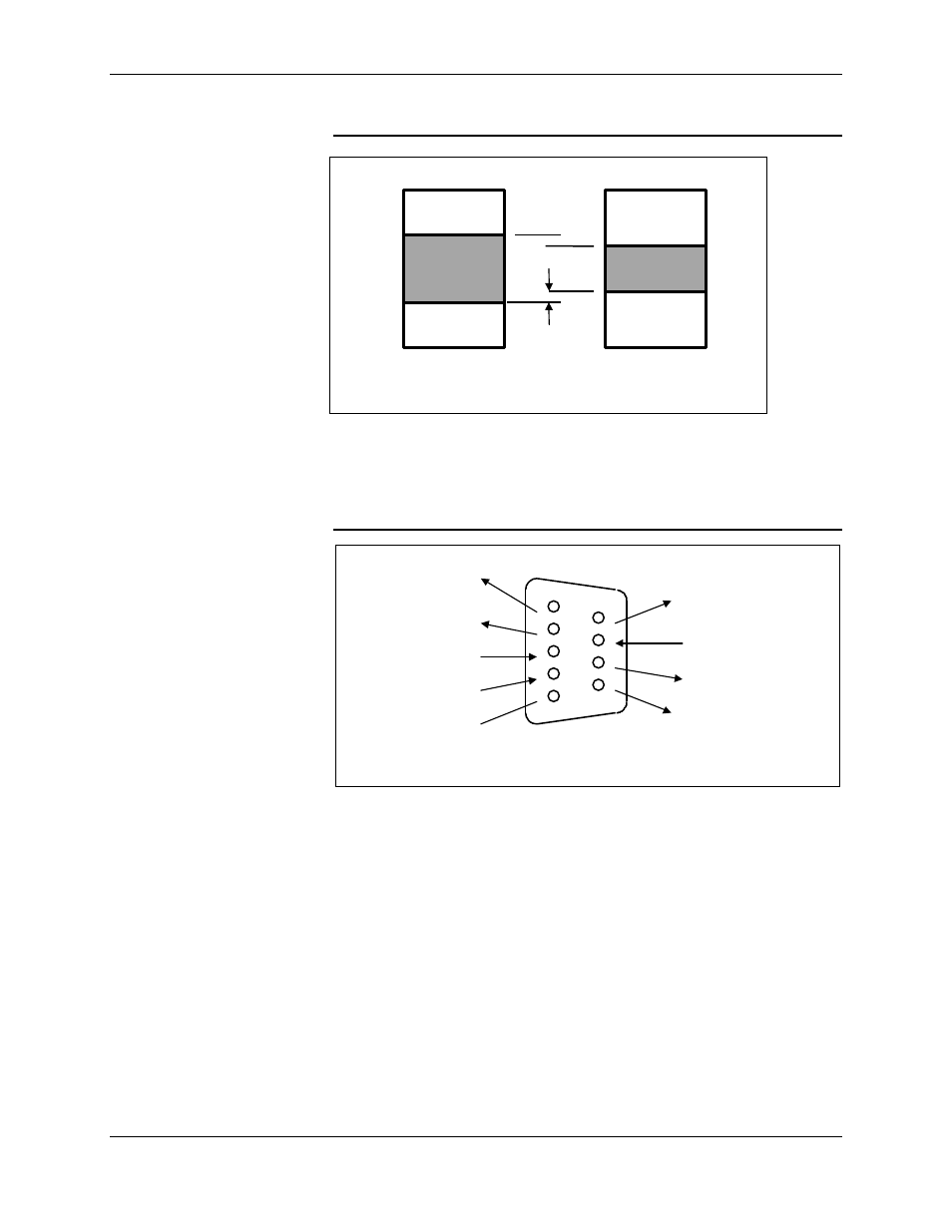
Figure 3-2 RS-232-C Voltage Specifications
The MP215 is configured as a DCE (Data Communications Equipment) and the
DB-9 connector uses the standard pin designations as shown in Figure 3.3.
Figure 3-3 Modem DB9 Pin Designation
3.2. Power Supply Interface and On/Off Control
The power supply connector for the MP215 is a Molex Connector P/N: 39-29-
1048. The pin designation for the mating connector (Molex P/N: 39-01-2040 or
39-01-2045, pins Molex P/N: 39-00-0039) is given in Figure 3-3.
-15 V
RS-232-C
driver
RS-232-C
receiver
Space
Logic 0
Mark
Logic 1
Space
Logic 0
Mark
Logic 1
Transition
region
Transition
region
+15 V
+15 V
+5 V
-5 V
-15 V
+3 V
-3 V
2 V noise
margin
1
2
3
4
5
6
7
8
9
Received Line
Signal Detect (DCD)
Transmitted Data
(TXD)
Received Data (RXD)
DTE Ready (DTR)
Signal Ground (GND)
DCE Ready (DSR)
Clear To Send (CTS)
Request To Send (RTS)
Ring Indicator (RI)
DB-9 Female