Assembly instructions – Stamina Products 55-2010 User Manual
Page 8
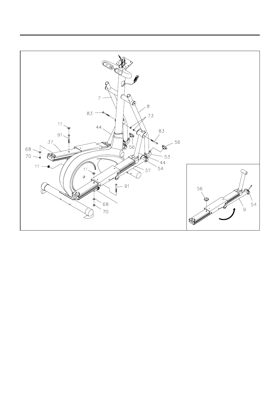
ASSEMBLY INSTRUCTIONS
8
STEP 4
Connect the
SUPPORT ARM(44)
to the
RIGHT PIVOTING ARM(8)
with
BUTTON HEAD BOLT
(M8x85mm)(83)
and
NYLOCK NUT(M8)(73).
STEP 5
Refer to the inset drawing. Remove the
LOCKING KNOB(56)
from the
LINKAGE CONNECTOR(54).
Then swing the
LINKAGE(9)
toward the front. Insert the the
LINKAGE CONNECTOR(54)
through the
CONNECTOR(53)
and secure with the
LOCKING KNOB(56).
Press the
CRANK CAP(11)
into the
hole on the
PEDAL RAIL(37).
STEP 6
Attach the
PEDAL RAIL(37)
to the
RIGHT RAIL CONNECTOR(61)
with
BUTTON HEAD BOLT
(M10 x 85mm)(91), WASHER(M10)(68),
and
NYLOCK NUT(M10)(70).
Repeat the above steps on the left side.
(61) RIGHT RAIL CONNECTOR
The rectangular part points to
the rear.