Star Micronics SLIP SP298 User Manual
Page 15
12
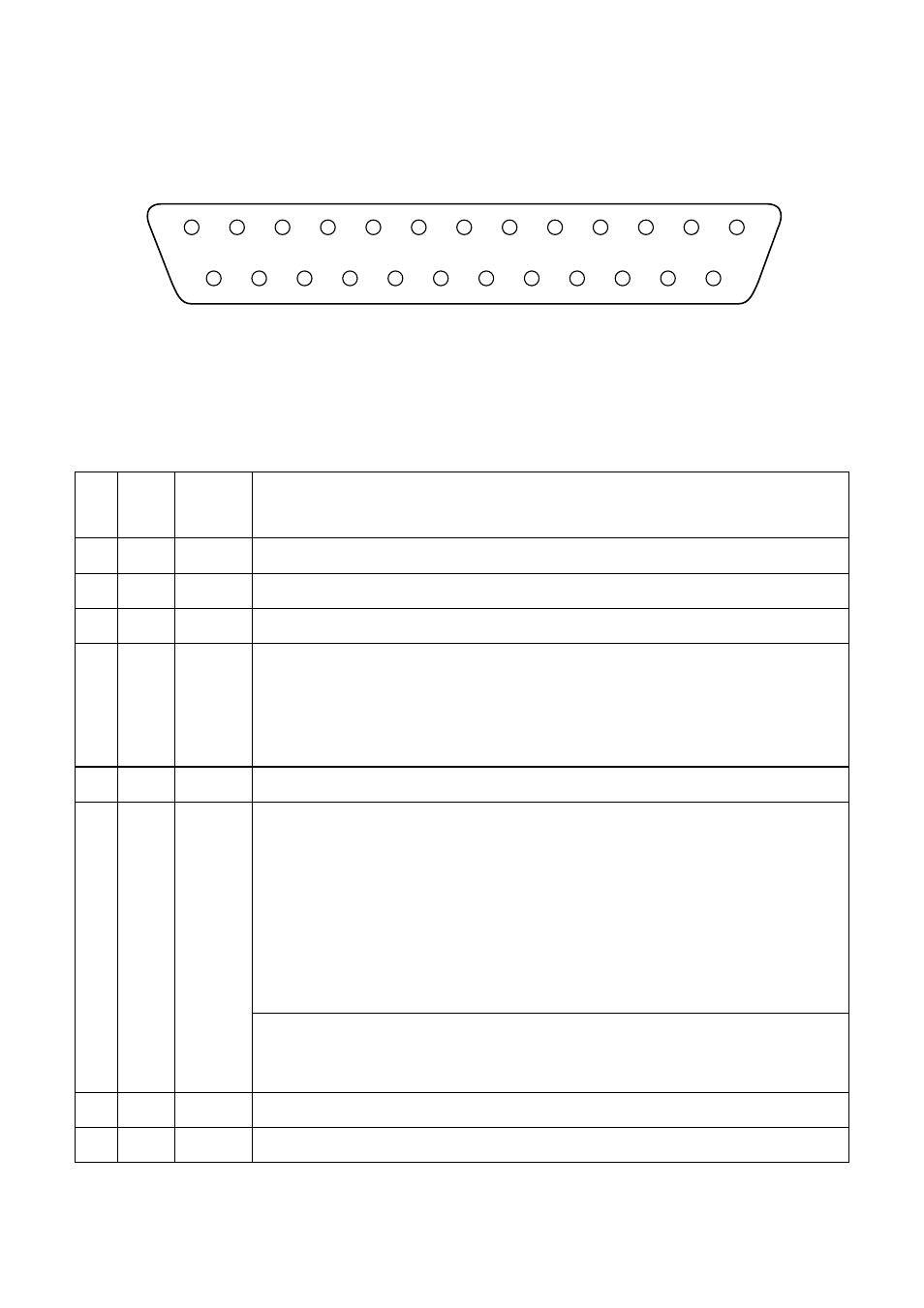
Serial interface pins and signal names
Pins and Signal Names
Pin
No.
Signal
Name
Direction
Function
1
FG
—
Frame ground
2
TXD
OUT
Transmission data
3
RXD
IN
Receive data
4
RTS
OUT
STAR Mode
When Memory Switch 4-D = 0: Same as DTR signal
When Memory Switch 4-D = 1: Always SPACE
ESC/POS Mode
Same as DTR signal
5
N.C.
Not connected
6
DSR
IN
• DIP Switch 9 = OFF
STAR Mode
Status of this signal is not checked.
ESC/POS Mode
In DTR/DSR communication mode when Memory Switch4-5 = 0, indicates whether data
receive from host is enabled or disabled.
Space: Receive enabled
Mark: Receive disabled
This signal is not checked in the X-ON/X-OFF communication mode.
• DIP Switch 9 = ON
This signal used for external reset. Printer is reset whenever signal is in mark state with
pulse width of 1mS or more.
7
SG
Signal ground
8 -19
N.C.
Not connected
13
25
1
14
- LC-90 (131 pages)
- LC-240C (82 pages)
- MP500 Series (2 pages)
- Star SP317 (63 pages)
- SP200F (111 pages)
- NL-10 (35 pages)
- MP115MP-24G-A (42 pages)
- LC-6211 (60 pages)
- 800C (76 pages)
- LC-1021 (91 pages)
- SP200F SERIES (90 pages)
- SP200F SERIES (114 pages)
- 150 (151 pages)
- LC-1011C (88 pages)
- RS232 (80 pages)
- FUTUREPRINT TSP100 (32 pages)
- SP700 Series (2 pages)
- DP8340RC (40 pages)
- SP342F-A (62 pages)
- PR921-24-A (31 pages)
- SP312F (36 pages)
- SP300 Series (70 pages)
- SP317 (63 pages)
- SP2000 Series (147 pages)
- LC-8021 (86 pages)
- NP-325 (45 pages)
- DP8340 (59 pages)
- PW2000-24 (4 pages)
- HL 80825321 (176 pages)
- Line Thermal Printer (181 pages)
- PUNKT-MATRIX-DRUCKER LC-7211 (182 pages)
- Automatic Sheet Feeder SF-15HA (42 pages)
- Star futurePRNT TSP100GT (2 pages)
- Star SP200 Series (127 pages)
- PT-10Q (36 pages)
- SP298 Series (144 pages)
- LC-8521 (116 pages)
- RSR 28 (5 pages)
- SP320S (94 pages)
- Dot Impact Printer (104 pages)
- LC-4521 (191 pages)
- PT-10Y (32 pages)
- Line Thermal/Dot Printer (209 pages)
- ATAR LC-500 (72 pages)