Communications protocol – Sanyo VCC-MD500 User Manual
Page 11
− 10 −
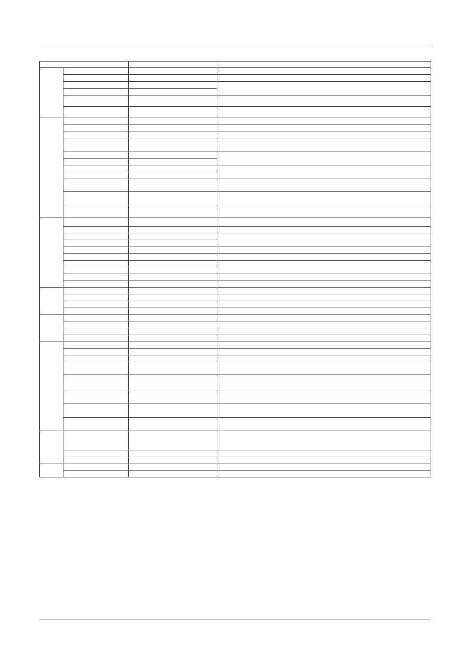
Message
Sync
Sync INT
A0 09 00 CS FF
Internal synchronization mode
Sync L-L
A0 09 01 CS FF
Power supply synchronization mode
L-L Phase +
A0 09 0B CS FF
Synchronous phase settings for power source synchronization
L-L Phase -
A0 09 0C CS FF
L-L Phase Preset
A0 09 0F CS FF
Returns synchronous phase settings for power source synchronization to factory defaults
(Initial value: 0)
L-L Phase Direct
A0 09 13 0p 0q 0r CS FF
pqr: Synchronous phase settings for power source synchronization
Direct 0-524 (NTSC) / 0-624 (PAL) (Initial value: 0)
AGC
COLOR MAX Gain
A0 0A 00 0p CS FF
p: AGC MAX Gain settings during COLOR (0: LOW, 1: NORM, 2: MID, 3: HIGH)
B/W MAX Gain
A0 0A 01 0p CS FF
p: AGC MAX Gain settings during B/W (0: LOW, 1: NORM, 2: MID, 3: HIGH)
AUTO MAX Gain
A0 0A 02 0p CS FF
p: AGC MAX Gain settings during AUTO (1: NORM, 2: MID, 3: HIGH)
AGC ON/OFF
A0 0A 03 0p CS FF
p: AGC ON/OFF switch (Cannot be set to OFF when D/N AUTO or when SENSE UP setting is enabled)
(0:OFF, 1:ON)
(Note 3)
COLOR AGC_OFF Gain +
A0 0A 0B CS FF
Gain settings when COLOR and AGC are OFF (Initial value: 0dB)
COLOR AGC_OFF Gain -
A0 0A 0C CS FF
B/W AGC_OFF Gain +
A0 0A 0D CS FF
Gain settings when B/W and AGC are OFF (Initial value: 0dB)
B/W AGC_OFF Gain -
A0 0A 0E CS FF
Gain Preset
A0 0A 0F CS FF
Returns gain settings when AGC is OFF to factory defaults
(D/N camera is both COLOR and B/W) (Initial value: 0dB)
Gain Direct (COLOR)
A0 0A 12 0p CS FF
p: Gain settings when COLOR and AGC are OFF
(0: 0dB, 1: 3dB, 2: 6dB, 3: 9dB, 4: 12dB, 5: 15dB, 6: 18dB, 7: 21dB, 8: 24dB, 9: 27dB, 10: 30dB)
Gain Direct (B/W)
A0 0A 13 0p CS FF
p: Gain settings when B/W and AGC are OFF
(0: 0dB, 1: 3dB, 2: 6dB, 3: 9dB, 4: 12dB, 5: 15dB, 6: 18dB, 7: 21dB, 8: 24dB, 9: 27dB, 10: 30dB)
Aperture
OFF
A0 0B 00 CS FF
ON
A0 0B 01 CS FF
Aperture V +
A0 0B 0B CS FF
Vertical contour compensation settings
Aperture V -
A0 0B 0C CS FF
Aperture V Preset
A0 0B 0F CS FF
Returns vertical contour compensation settings to factory defaults (Initial value: 8)
Aperture V Direct
A0 0B 13 0p CS FF
p: Vertical contour compensation settings 1-15 (Initial value: 8)
Aperture H +
A0 0B 15 CS FF
Horizontal contour compensation settings (Initial value: 8)
Aperture H -
A0 0B 16 CS FF
Aperture H Preset
A0 0B 19 CS FF
Returns horizontal contour compensation settings to factory defaults (Initial value: 8)
Aperture H Direct
A0 0B 1D 0p CS FF
p: Horizontal contour compensation settings 1-15 (Initial value: 8)
Gamma
OFF
A0 0C 00 CS FF
Gamma OFF (1)
ON
A0 0C 01 CS FF
Gamma ON (0.45)
SMART1
A0 0C 02 CS FF
Gamma SMART1 (Increases the contrast of dark sections)
SMART2
A0 0C 03 CS FF
Gamma SMART2 (Further increases the contrast of dark sections)
Mirror
OFF
A0 0D 00 CS FF
Canceling Inversions
H-Mirror
A0 0D 01 CS FF
Horizontal inversion (Cancels vertical inversion)
V-Mirror
A0 0D 02 CS FF
Vertical inversion (Cancels horizontal inversion)
HV-Mirror
A0 0D 03 CS FF
Vertical and horizontal inversions
Privacy
Masking
Area Mask OFF
A0 10 00 0p CS FF
p: Mask number 1-15 (All OFF when 0)
Area Mask ON
A0 10 01 0p CS FF
p: Mask number 1-15 (All ON when 0) * Up to 4 masks can be displayed on a single-screen.
Privacy Mask Move
A0 10 02 00 0p CS FF
p: Privacy mask angle link (0: OFF, 1: ON) * When set to OFF only Mask numbers 1 – 4 can be used.
Area Mask Position Clr
A0 10 05 0p CS FF
p: Mask number 1-15 (ALL CLEAR when 0)
*Only the "Position setting" is cleared. To make the mask display off, set the Area mask to OFF.
Area Mask Position Set
A0 10 09 0p 0q 0r 0s 0t 0u Sets the positioning of the mask. Refer to the Privacy
Refer to "Function Descriptions [11]Privacy Mask Setting"
0v 0w 0x CS FF
Area Mask Position Center Set A0 10 0A 0p 0q 0r 0s 0t CS Sets the mask to the center of the optical axis. (p: mask number 1-15)
FF
Area Mask Position Full Screen
Set
A0 10 0B 0p CS FF
Mask is set the full screen being displayed (p: mask number 1-15)
Area Mask Degree Set
A0 10 11 0p 0q 0r 0s xt
0u p: Mask No 1-8, qrs: Pan Degree tuv: Tilt Degree * Degree increased x10 and the value input is
converted to a hexadecimal number. x: Tilt angle sign bit
0v CS FF
Pan/Tilt
Degree
Pan/Tilt Degree
A0 11 00 0p 0q 0r xs 0t 0u Current positioning information settings when installing dome camera * The degree is magnified x10,
inputs the value changed to a hexadecimal number. pqr: Pan Degree, stu:Tilt Degree, x: Tilt angle sign
bit
(Note 9)
CS FF
Auto Mask Pos. OFF
A0 11 0A CS FF
Privacy mask is set to the information of Pan/TiltDegree positioning and is not moved
Auto Mask Pos. ON
A0 11 0B CS FF
Privacy mask is set to the information of Pan/TiltDegree positioning and is moved
STILL
OFF
A0 12 00 CS FF
ON
A0 12 01 CS FF
Sets the current image to still.
Communications Protocol
Model: VCC-MD800/700/600/500
CS: Checksum
FF: Terminator