Back panel terminals – Sony SAT-W60 User Manual
Page 25
Other Information
25
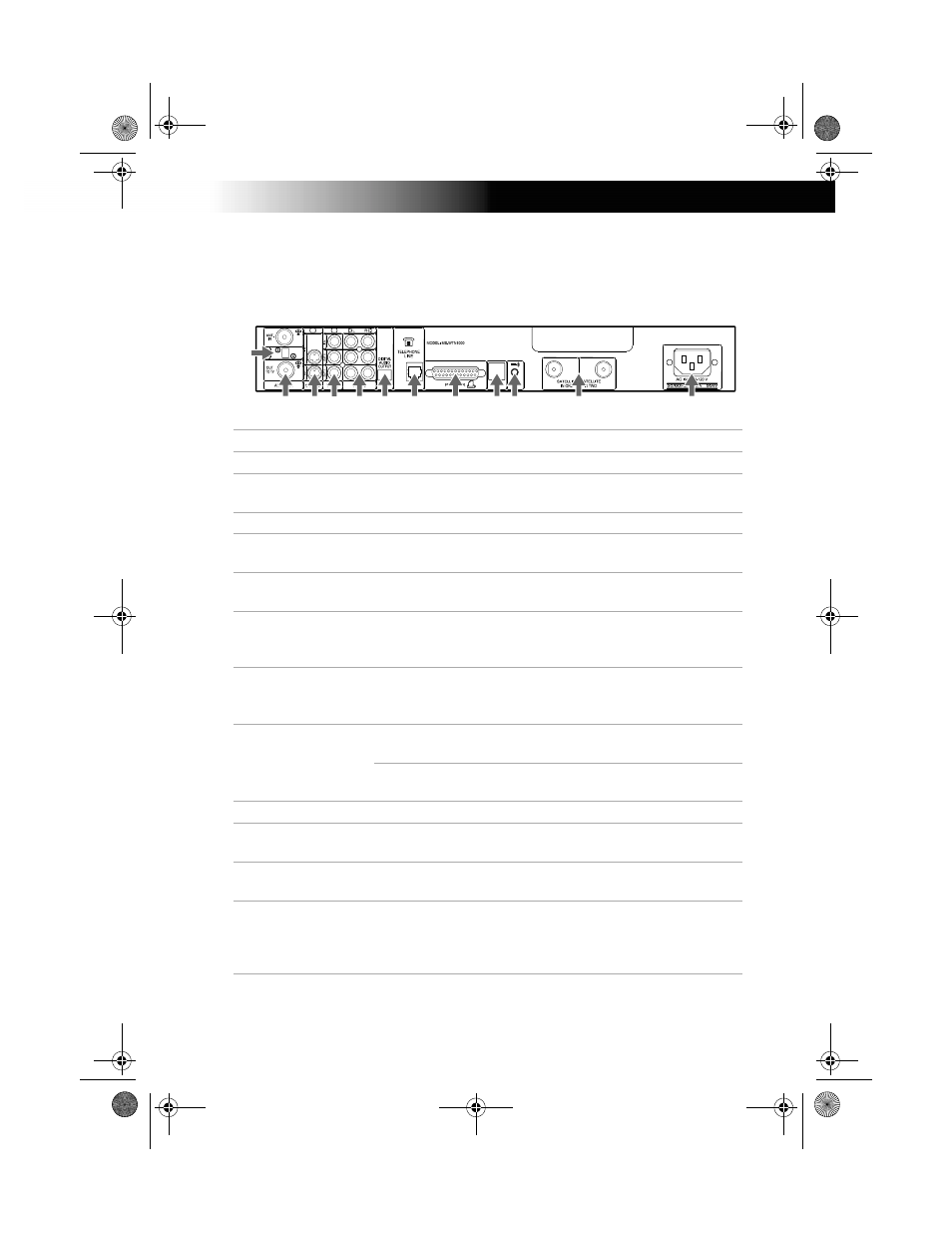
Back Panel Terminals
Connector
Description
1
TELEPHONE LINE Connects your receiver/recorder to a telephone jack.
2
VCR CONTROLLER Allows you to connect your IR Blaster for easy control of
your cable box and/or VCR through the receiver/recorder.
3
PRINTER PORT
Allows you to connect your receiver/recorder to a printer.
4
AUDIO (R)/(L)
IN/OUT
Connects your receiver/recorder to the right and left
audio inputs and outputs of your TV.
5
VIDEO IN/OUT
Connects your receiver/recorder to your TV’s or VCR’s
video inputs and outputs.
6
S-VIDEO IN/OUT
Allows you to connect your receiver/recorder to your TV
and VCR for optimal picture quality (if your TV and VCR
support S-Video.
7
CH 3-CH 4 Switch The switch determines which TV channel allows you to
view programs from your receiver/recorder when
connected through the VHF/UHF connector.
8
VHF/UHF
IN: Allows you to connect your normal (antenna) TV or
cable TV service to your receiver/recorder.
OUT: Allows you to send normal (antenna) TV or cable
signals to your TV or VCR from your receiver/recorder.
9
AC IN
Connects your receiver/recorder to a 120V AC outlet.
0
DIGITAL AUDIO
OUTPUT
Allows you to connect an optional digital audio system.
qa
USB Port
Allows you to connect Universal Serial Bus components,
such as a keyboard or a digital camera.
qs
SATELLITE IN
Connect the cable from your satellite dish antenna here.
Connect a second cable if you wish to use both of the
receiver/recorder’s tuners, this allows features such as PIP
and recording one show and while viewing another.
Digital Satellite Receiver/Recorder
0
qa
qs
2
1
4
3
5
6
7
8
9
01USBook.BOOK Page 25 Wednesday, July 5, 2000 12:24 PM