Connection – Sanyo MPX-MD162 User Manual
Page 6
CONNECTION
Before making any connection, make sure all the devices are turned off.
Before making the connections, please refer to the instruction manual accompanying each device. If the devices are not connected
properly, that may cause a fire and/or damages.
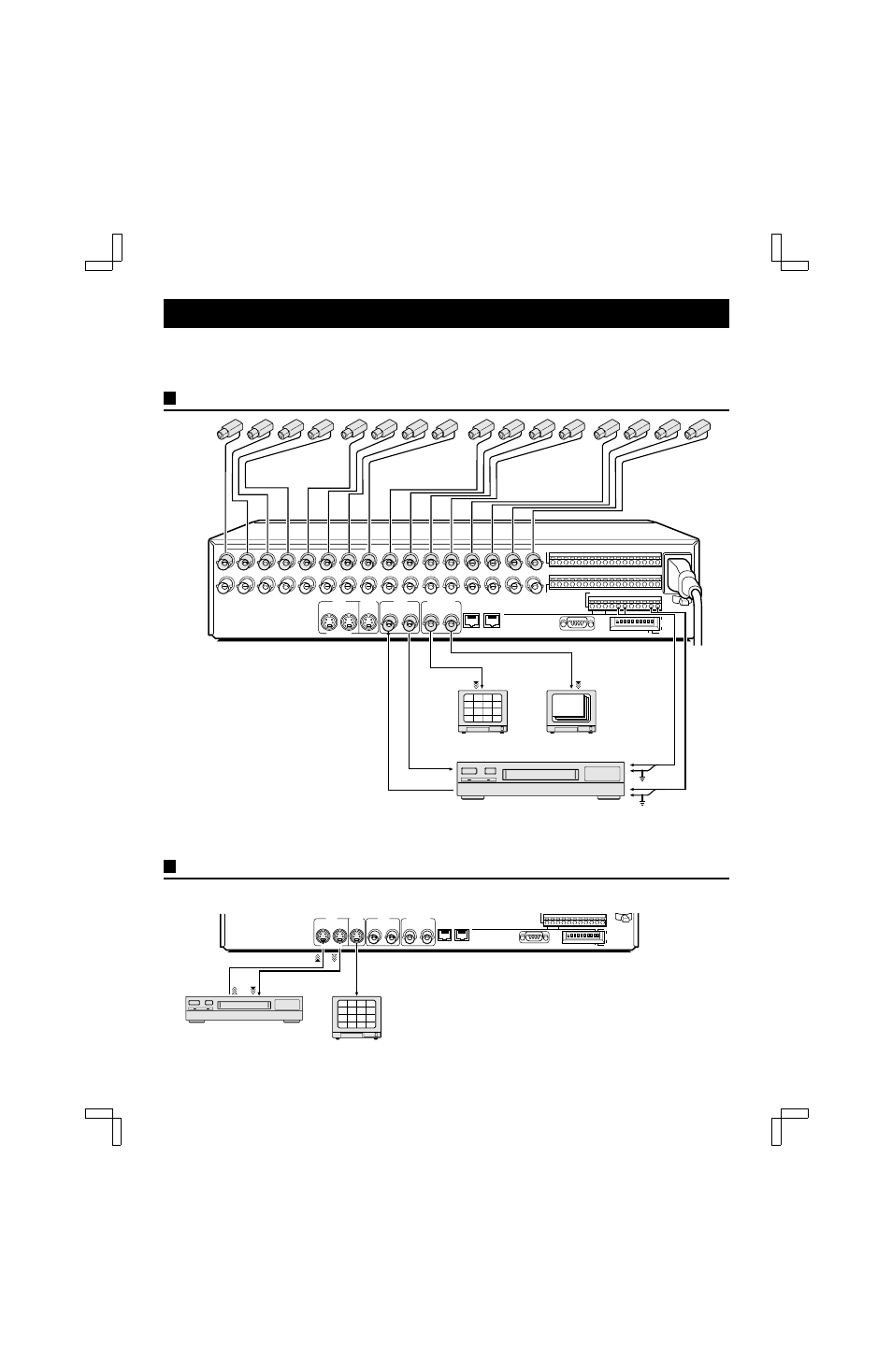
BASIC CONNECTIONS
CONNECTIONS TO THE S-VIDEO TERMINALS
If connections are made to the S-VIDEO terminals, they will have the priority.
RS232C
1 2 3 4 5 6 7 8 9 10 11 12 13 14
1
2
3
15 16
C
4
5
6
7
8
9
10
11
12
13
14
15
16
C A B C AL C R1 R2 C SW C
1
2
3
4
5
6
7
8
9
10
ON
VCR
VCR
S-VIDEO
1
1
2
A
B
RS485
485
ON
OFF
232
CAMERA
MONITOR
MONITOR
IN
IN
OUT
OUT
OUT
IN
ALARM IN
CONTROL
SENSOR ALARM
OUT
ADDRESS
TERMI
NATE
1
2
5
6
3
4
7
8
9
10
13
14
11
12
15
16
Monitors (sold separately)
Video input
terminal
Ground
Ground
ALARM input
terminal
Video input
terminal
Timelapse VCR (sold separately)
Switching output
terminal
NOTE:
The camera signal input at each CAMERA IN
terminal is throughput at the corresponding
CAMERA OUT terminal. The CAMERA IN
terminals are automatically terminated at 75
Ω
.
• When no connection is made to the CAMERA
OUT terminal, the CAMERA IN terminal 75
Ω
termination is made automatically.
• When a connection is made to the CAMERA
OUT terminal, the CAMERA IN terminal
termination is open, you must therefore make
sure the CAMERA OUT side is terminated.
• With model MPX-MD162, use black and white
cameras only. If color cameras are used, that
may cause image beat, etc.
RS232C
A
B
RS485
485
ON
OFF
232
S-VIDEO
CONTROL
ADDRESS
TERMI
NATE
Timelapse VCR (sold separately)
S-VIDEO output
terminal
S-VIDEO input
terminal
S-VIDEO
S-VIDEO input
terminal
1
2
5
6
3
4
7
8
9
10
13
14
11
12
15
16
VCR
VCR
1
1
2
MONITOR
MONITOR
IN
IN
OUT
OUT
L8FC5/US (MPX-CD162, MD162 GB) 2000. 8. 31
English
5