Menu 3, Serial set) – Sanyo MPX-MD162 User Manual
Page 31
VCR SETTING AND EXTERNAL CONTROL COMMUNICATION
SPEED SETTING
Menu 3
If the VCR is Equipped with a SW (switching) Output
Connector (using the VCR switching signal)
Make the connection from this unit to the VCR SW output
connector. The video signal output by this unit will be
automatically switched to the recording speed according to the
switching signal output by the VCR (switching pulse setting on
the VCR).
The (VCR SET) menu “REC SPEED” and “ALARM REC
SPEED” items do not need to be set.
If a switching signal is not output at the switching terminal
Some VCR models may not output a switching signal in 2H or
6H mode. In such a case, make the settings as indicated in the
table below.
VCR SET menu settings
Timelapse VCR
Real time VCR
REC SPEED
2 (2H)
6 (6H)
ALARM REC SPEED
F2
F6
NOTE: When the recording speed is set to F2 or F6, the alarm
recording speed is fixed to 2H or 6H. Therefore, when
using a recording speed other than 2H or 6H, do not use
the F2 or F6 setting.
(SERIAL SET)
Connect the multiplexer to a computer, using a 9-pin D-SUB
cable (sold separately), then set the maximum communication
speed between the unit and the computer.
For detailed information, please refer to “INTERFACE
SPECIFICATIONS” on page 48.
Setting the RS232C/RS485 communication
1
Press the
l
button to highlight the setting to modify.
2
Using the + (or –) button, select the desired “DATA
SPEED” setting, then press the
l
button.
3
Using the + (or –) button, select the desired “ALARM
SEND” setting.
4
☞
Press the MENU button to go to the next menu
screen, or
☞
Press the EXIT button to exit the menu display.
SERIAL SET menu
DATA SPEED
(Default setting: 19200 bps)
The available settings are: 2400, 4800, 9600, 19200 bps
ALARM SEND
(Default setting: OFF)
ON: The alarm information is output at the RS232C/RS485
terminals.
OFF: The alarm information is not output at the RS232C/RS485
terminals.
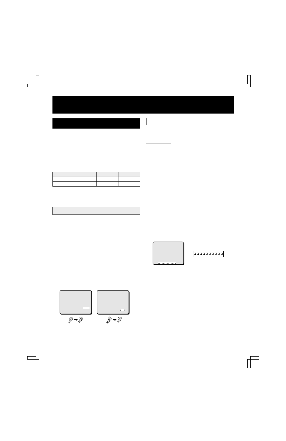
Unit address confirmation
If multiple units are going to be controlled through a system
controller (sold separately) via the RS485 connection, each unit
must have a address for remote control purposes. The address
set for the unit can be checked by accessing the (VCR SET)
menu.
1
Press the MENU button three times to display the (VCR
SET) menu.
The unit address is displayed on the last line of the menu.
The unit address can be set using the Interface setting DIP
switches on the back panel of the unit. (see page 49)
2
☞
Press the MENU button to go to the next menu
screen, or
☞
Press the EXIT button to exit the menu display.
2
3
(VCR SET)
VCR MODE TLS
REC SPEED 2 H
ALARM REC SPEED 2 H
PROGRAM REC MODE OFF
COLOR KILLER OFF
(SERIAL SET)
DATA SPEED 19200
ALARM SEND OFF
ööADDRESS:000öö
(VCR SET)
VCR MODE TLS
REC SPEED 2 H
ALARM REC SPEED 2 H
PROGRAM REC MODE OFF
COLOR KILLER OFF
(SERIAL SET)
DATA SPEED 19200
ALARM SEND OFF
ööADDRESS:000öö
1
Address (000 – 127)
(VCR SET)
VCR MODE TLS
REC SPEED 2 H
ALARM REC SPEED 2 H
PROGRAM REC MODE OFF
COLOR KILLER OFF
(SERIAL SET)
DATA SPEED 19200
ALARM SEND OFF
ööADDRESS:000öö
1
2
3
4
5
6
7
8
9
10
ON
ON
OFF
(Interface setting DIP switches)
L8FC5/US (MPX-CD162, MD162 GB) 2000. 8. 31
30
English