7 connector defi nitions – SUPER MICRO Computer SUPERO H8QG6+-F User Manual
Page 36
H8QG6/i+-F Serverboard User's Manual
2-10
2-7 Connector
Defi nitions
Power Connectors
A 24-pin main power supply connector(JPW1)
and three 8-pin CPU PWR connectors
(JPW2/JPW3) on the motherboard. These
power connectors meet the SSI EPS 12V
specifi cation. In addition to the 24-pin ATX
power connector, the 12V 8-pin CPU PWR
connectors at JPW2/JPW3 must also be
connected to your power supply. See the
table on the right for pin defi nitions.
Warning: To prevent damage to the power
supply or motherboard, please use a power
supply that contains a 24-pin and three
8-pin power connectors. Be sure to connect
these connectors to the 24-pin (JPW1) and
the three 8-pin (JPW2 and JPW3) power
connectors on the motherboard. Failure in
doing so will void the manufacturer warranty
on your power supply and motherboard.
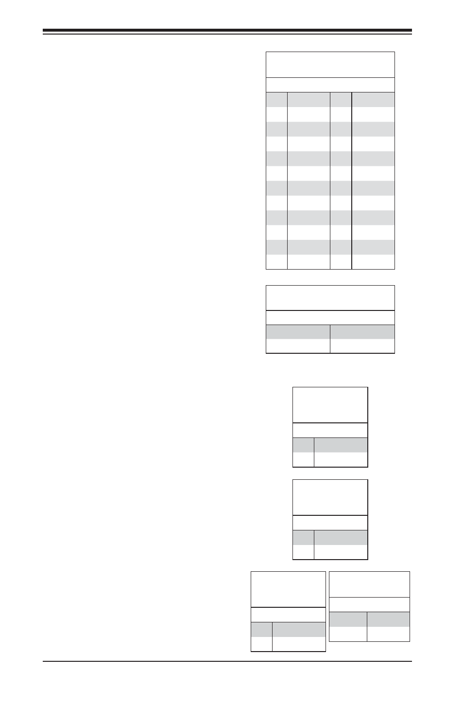
ATX Power 24-pin Connector
Pin Defi nitions
Pin# Defi nition Pin # Defi nition
13
+3.3V
1
+3.3V
14
-12V
2
+3.3V
15
COM
3
COM
16
PS_ON
4
+5V
17
COM
5
COM
18
COM
6
+5V
19
COM
7
COM
20
Res (NC)
8
PWR_OK
21
+5V
9
5VSB
22
+5V
10
+12V
23
+5V
11
+12V
24
COM
12
+3.3V
12V 8-pin PWR Connector
Pin Defi nitions
Pins Defi nition
1 through 4
Ground
5 through 8
+12V
Required Connection
Reset Connector
The reset connector is located on pins 3 and
4 of JF1 and attaches to the reset switch on
the computer chassis. See the table on the
right for pin defi nitions.
PW_ON Connector
The PW_ON connector is on pins 1 and 2 of
JF1. This header should be connected to the
chassis power button. See the table on the
right for pin defi nitions.
Reset Button
Pin Defi nitions
(JF1)
Pin# Defi nition
3
Reset
4
Ground
Power Button
Pin Defi nitions
(JF1)
Pin# Defi nition
1
PW_ON
2
Ground
Overheat/Fan Fail LED (OH)
Connect an LED to the OH connection on
pins 7 and 8 of JF1 to provide advanced
warning of chassis overheating or fan
failure. Refer to the table on the right for pin
defi nitions and status indicators.
OH/Fan Fail LED
Pin Defi nitions
(JF1)
Pin# Defi nition
7
Vcc
8
Control
OH/Fan Fail
LED Status
State Indication
Solid
Overheat
Blinking
Fan fail