9 head voltage, 10 peak current – Seiko Instruments LTP F Series User Manual
Page 40
3-22
3.5.9 Head
Voltage
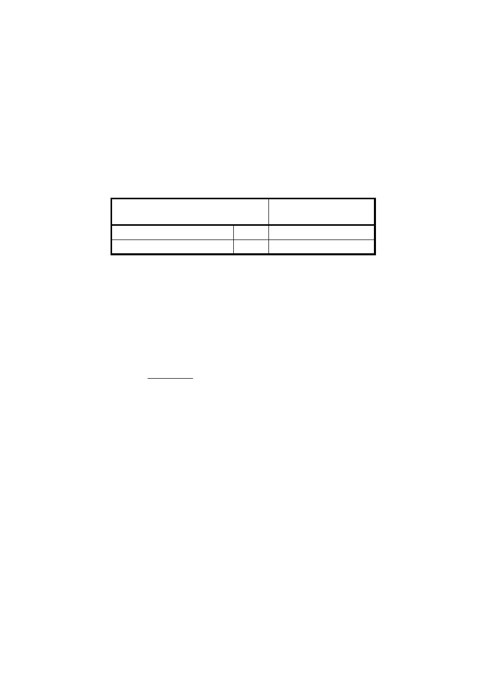
The printer has a built-in head driver IC. Table 3-11 shows the head voltage.
Table 3-11 Head Voltage
Item
Voltage Range
Head drive voltage
V
P
21.6 to 26.4 V
Head logic voltage
V
dd
4.75 to 5.25 V
3.5.10 Peak
Current
Since the peak current (maximum current) may reach the values calculated using equation (1) when
the thermal head is driven, make sure that the allowable current for the cable material and the voltage
drop on the cables are well within the specified range.
Equation (1):
I
P
=
I
P
:
Peak current (A)
N:
Number of dots that are driven at the same time
V
P
: Head drive voltage (V)
RH: Head resistance (
Ω)
N
× V
P
RH