4 structure of the thermal head (ltpf347) – Seiko Instruments LTP F Series User Manual
Page 36
3-18
3.5.4 Structure of the Thermal Head (LTPF347)
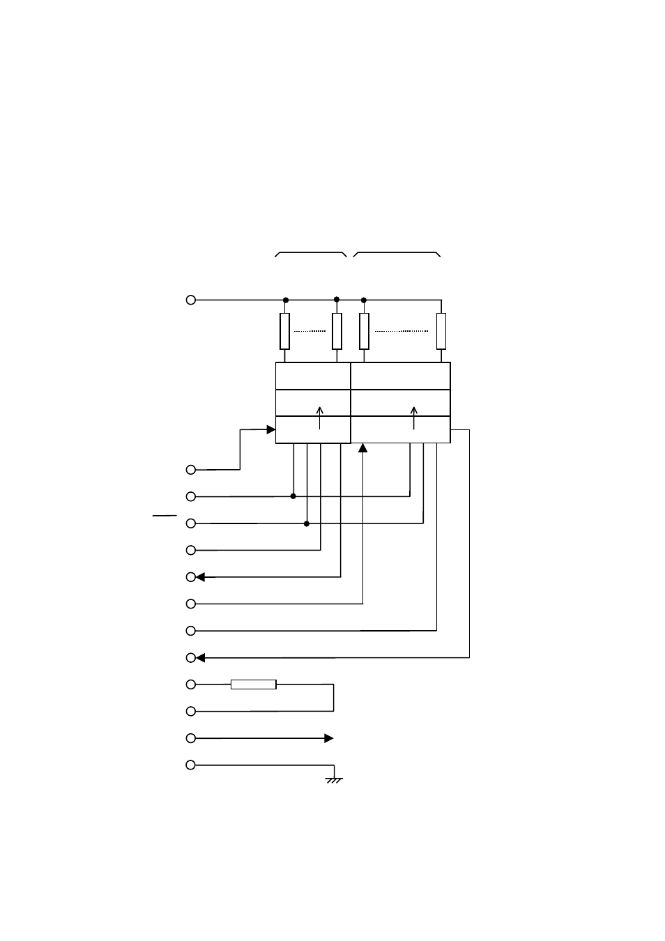
Figure 3-11 shows the thermal head block diagram for the LTPF347.
Table 3-8 shows the relationship between DST blocks and activated heat elements.
Figure 3-11 Thermal Head Block Diagram (LTPF347)
DAT IN2
CLK
LATCH
DST2
DAT OUT2
TH
TH
Vdd
GND
Output driver
Latch register
Shift register
Heat elements
Vp
DOT640
DOT385
DOT384
DOT
1
Thermistor
Block 2
Block 1
DAT IN1
DAT OUT1
*1
*1
N.C. if not using DAT OUT
DST1
*1