Introduction, Principle schematic, Description of main functions – Studer Innotec XPC 1112 User Manual
Page 6: The inverter, The transfer system, The battery charger, Rinciple schematic, Escription of main functions, 2 introduction, 1 principle schematic
STUDER INNOTEC
XP-COMPACT
2 Introduction
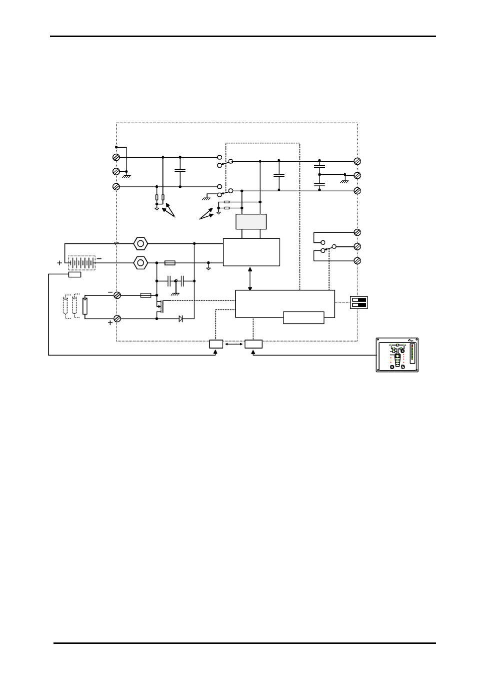
The XP-COMPACT is a sine wave inverter with integrated battery charger and solar charge con-
troller with many additional functions, it has been developed to be used as stand-alone (no grid
feeding) AC provider, or as continuous / break-free current supply provider (UPS).
2.1 Principle
schematic
6p
8p
RJ11
OFF
AC OUT
Over Temp.
Overload
AC IN
SOLAR CHARGE
Contact manual
Contact active
Program
COMPACT
AUXILIARY
CONTACT
ON/ OFF
INVERTER - CHARGER
(Select)
RCC-01
INVERTER
CHARGER
(Program)
(Change status)
Battery
Low/High
RESET
ALARM
10
20
30
40
50
60
70
TRANSFER
Ch
arg
er
Inv
ert
er
5
10
20
40
60
80
100
130
160
A
%
EQUALIZE
SOLAR
AUX. CONT.
L
PE
N
L
PE
N
Remote control
BATTERY
CT35
100nF
1uF
10nF
10nF
1uF
150A
1uF
4x2,7M
Ω
Remote control
Temp.
Max
.
6m
Max. 40m
AC OUT
Filter
Microprocessor,
Control, Adjustment
Display
Inverter
Charger
Remote control
Solarmodule
Temp. Sensor
Battery
Input
230Vac
Output
230Vac
AC IN
2.2 Description of main functions
2.2.1 The
inverter
The sinewave inverter built in the XP-COMPACT generates a sinusoidal AC voltage with an excep-
tionally precise voltage and stabilized frequency. In order to start large electric motors, the user
has the possibility to employ a short-start-power which is 3-times the nominal power of the XP-
COMPACT.
The inverter is protected against overload and short-circuits. A power stage with the latest MOS-
FET power transistors, a toroidal transformer and a fast regulating system make-up a robust and
reliable inverter with highest efficiency. A 1-20 Watt adjustable charge detection system serves to
provide the smallest energy consumption and ensures a long life for the battery.
2.2.2 The transfer system
XP-COMPACT can be connected to an AC source, for example a stand-by emergency generator
or the AC network. With the transfer system, on one side you have an alternating voltage at the
output for use by the connected consumer appliances. On the other side the batteries are charged.
The distribution of energy between the consumer appliances and battery charger is automatic.
2.2.3 The battery charger
The built-in battery charger is so designed that it can charge the battery quickly and fully. A micro-
processor controlled, 3 to 4 Step charging process ensures the optimum charging of the batteries.
The desired charging current can be set continuously from 0 to maximum, according with particular
User manual
XP-COMPACT V2.0 E
5