Battery condition, The battery charger, Cycle of charge – Studer Innotec XPC 1112 User Manual
Page 14: Attery charger
STUDER INNOTEC
XP-COMPACT
User manual
XP-COMPACT V2.0 E
13
perature synchronizes the relay with the alarm signal. In this way, for example, an emergency back
up system can be started without any break in the energy supply.
4.6.4 Battery
Condition
Deep discharging of the lead-acid batteries leads to high losses in capacity and early aging. This is
why battery condition is continuously controlled and supervised. With low voltage the inverter
switches off. The LED 12 „L/H Batt.“ is lit and the LED 13 „OFF“ blinks. When the battery voltage
gets up to 12.1V / 24.2V / 48.4V, the Inverter switches on automatically. One minute before the
Inverter switch off due to low voltage it gives out an acoustic alarm signal. If the Auxiliary Contact
has been programmed to detect the low voltage then it synchronizes the aux. contact with the
alarm signal. In this way, for example, an emergency back up system can be started without any
break in the energy supply.
The low voltage is set to 11.8V / 23.6V / 47.2V. These settings are standard for most batteries.
These voltage levels are maintained by the built-in Battery-Management-System of XP-COMPACT
by matching the load and the battery condition.
This setting is comparable with the levels of 10.8V/ 21.6V / 43.2, which are given for most batteries
on nominal load.
All voltage levels (equalization absorption floating and disconnection voltage), can be programmed
by mean of the optional remote control.
4.7 The Battery charger
4.7.1 Cycle of charge
The full automatic XP-COMPACT Battery Charger is adjusted at the factory so that most lead-acid
and lead-gel batteries can be charged to the maximum. As soon as the minimum alternating volt-
age for the AC IN set on the Turning Knob 23 is available at the input (LED 1 AC IN is lit), the
transfer switch is activated and the battery charger is switched on automatically (LED 2 on optional
RCC-01 is lit). The battery is fully automatically charged matching to the charge level, the pre-
settled voltage levels and the charge current. Thanks to the built-in Float Charge System, the bat-
teries can be left connected for unlimited time with the Battery Charger switched on.
During the charging phase the consuming appliances at the outlet AC OUT are continuously sup-
plied with power (LED 8 AC OUT is lit).
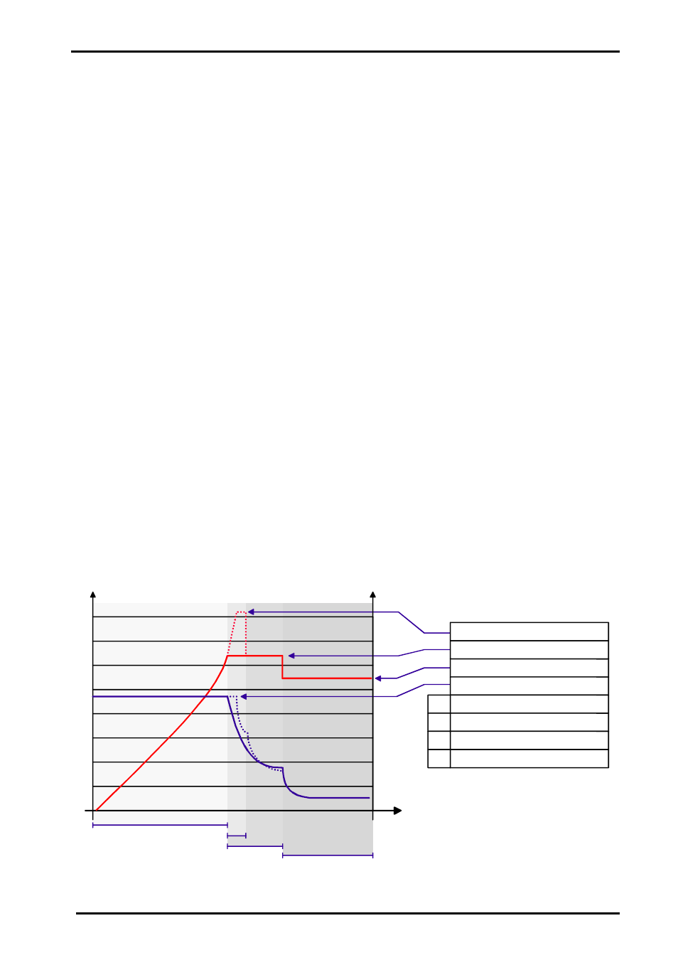
The charger functions are shown in the following diagram:
1.9
2.3
2.50
[V/cell]
2.1
A
B
C
D
20
60
40
70
[A]
A
B
C
D
t
Equalization
Absorption
Floating
Charging current (adjusted)
Charging time
Egalization time
Absorption time
Floating