Replacing the thermocouple, Replacing the pilot/ pilot tube assembly – State GS6 30 YOCT User Manual
Page 26
26
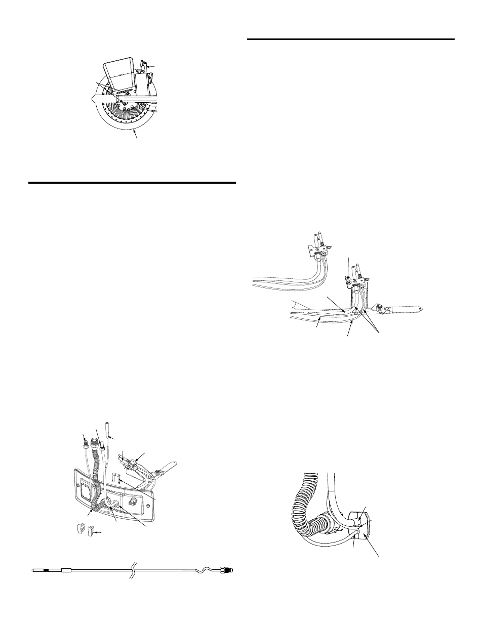
2. Check the burner to see if it is dirty or clogged. The burner
may be cleaned with soap and hot water (Figure 24).
BURNER
(BOTTOM VIEW)
SCREWS
PILOT ASSEMBLY
(BOTTOM VIEW)
FIGURE 24.
Replacing the Thermocouple
1. Remove the manifold/burner assembly as directed
previously.
2. Lift the retainer clip straight up from the back of the two
piece wire connector (using a flat-blade screwdriver),
then remove the two piece wire connector from the
manifold door (Figure 25.)
3. Remove the burner, see Removing the Burner from the
Manifold/Burner Assembly.
4. Pull the thermocouple from the pilot assembly (Figure 26).
IMPORTANT: Be careful not to bend or alter the position of
the pilot assembly components.
5. Insert the thermocouple tip into the holes provided in
the pilot bracket until it clicks into place. NOTE: The
base of the thermocouple must be flush with the base
of the pilot bracket.
6. Position the new thermocouple through the bottom
opening of the two piece wire connector (Figure 28).
Be sure igniter wire is positioned through the middle
opening of the two piece wire connector.
7. Re-attach the burner. Note the orientation of the buner
(Figure 24.)
8. See Replacing the Manifold/Burner Assembly.
OTHER FITTINGS
NOT SHOWN
FOR CLARITY
IGNITER WIRE
THERMOCOUPLE
TWO PIECE
WIRE CONNECTOR
RETAINER
CLIP
PILOT TUBE
PILOT BRACKET
PILOT
MANIFOLD TUBE
MANIFOLD/BURNER
DOOR OPENING
FERRULE NUT
FIGURE 25.
FIGURE 26.
Replacing the Pilot/ Pilot Tube Assembly
1. Remove the manifold/burner assembly. See Removing
the Manifold/Burner Assembly.
2. Lift the retainer clip straight up from the back of the two
piece wire connector (using a flat-blade screwdriver),
then remove the two piece wire connector from the
manifold door (Figure 25.)
IMPORTANT: Be careful not to bend or alter the position of
the pilot tube, it will be used as a bending template for the
new pilot assembly.
3. Take off the burner by removing the two (2) screws
located underneath the burner. See Figure 24.
4. Remove and keep the screw securing the pilot
assembly to the pilot bracket. (Figure 27)
5. Remove and keep the old pilot/pilot tube assembly.
6. Using the old pilot/pilot tube assembly as a guide, bend
the new pilot tube and new thermocouple to match the
old ones. NOTE: Make only the bends closest to the
pilot before going to the next step. (Figure 27)
FIRST BEND(S)
OTHER FITTINGS
NOT SHOWN
FOR CLARITY
PILOT TUBE
THERMOCOUPLE
IGNITER WIRE
SCREW
OLD PILOT ASSEMBLY
FIGURE 27.
7. Route the new pilot tube, thermocouple, and igniter wire
through the manifold/burner door opening. (Figure 25)
8. Re-attach the pilot assembly to the pilot bracket and
secure using the screw removed earlier.
9. Position the new pilot tube through the largest opening
of the two piece wire connector. NOTE: The largest
opening should be located at the top position. The
igniter wire should be located in the middle opening
and thermocouple in the bottom opening. (Figure 28)
TWO PIECE WIRE CONNECTOR
PILOT TUBE
IGNITER WIRE
THERMOCOUPLE
FIGURE 28.