Datasheet – SMSC USB2507 User Manual
Page 10
Integrated USB 2.0 Compatible 7-Port Hub
Datasheet
Revision 2.3 (08-27-07)
10
SMSC USB2507
DATASHEET
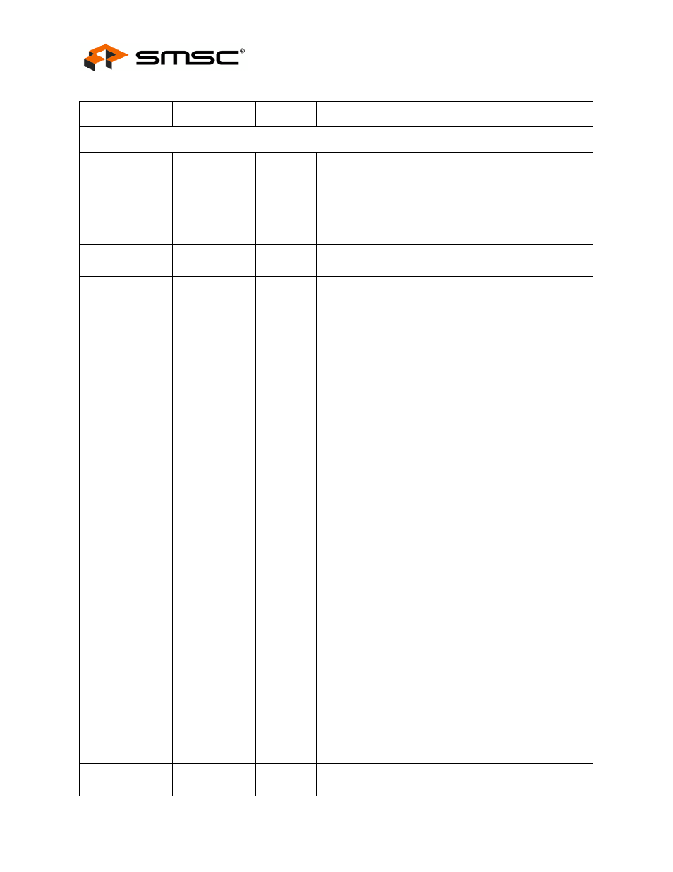
7-PORT USB 2.0 HUB INTERFACE
High-Speed USB
Data
USBDN[7:1]
USBDP[7:1]
IO-U
These pins connect to the downstream USB peripheral
devices attached to the Hub’s ports.
USB Power
Enable
PRTPWR[7:1]
O12
Enables power to USB peripheral devices (downstream).
The active signal level of the PRTPWR7:1 pins is
determined by the Power Polarity Strapping function of the
PRTPWR_POL pin.
Ports [7:5] Green
LED
GR[7:5]
I/O12
Green indicator LED’s for ports[7:5]. LED is active low
Port 4:3 Green
LED
&
Port Disable
strapping option.
GR[4:3]/
PRT_DIS[1:0]
I/O12
Green indicator LED for ports 4 and 3. Will be active low
when LED support is enabled via EEPROM or SMBus.
If the hub is configured by the internal default configuration,
these pins will be sampled at RESET_N negation to
determine if ports [7:5] will be permanently disabled. Also,
the active state of the LED’s will be determined as follows:
PRT_DIS[1:0] = ‘00’, All ports are enabled,
GR4 is active high,
GR3 is active high.
PRT_DIS[1:0] = ‘01’, Port 7 is disabled,
GR4 is active high,
GR3 is active low.
PRT_DIS[1:0] = ‘10’, Ports 7 & 6 are disabled,
GR4 is active low,
GR3 is active high.
PRT_DIS[1:0] = ‘11’, Ports 7, 6 & 5 are disabled,
GR4 is active low,
GR3 is active low.
Port [2:1] Green
LED
&
Port Non-
Removable
strapping option.
GR[2:1]/
NON_REM[1:0]
I/O12
Green indicator LED for ports 2 and 1. Will be active low
when LED support is enabled via EEPROM or SMBus.
If the hub is configured by the internal default configuration,
these pins will be sampled at RESET_N negation to
determine if ports [3:1] contain permanently attached (non-
removable) devices. Also, the active state of the LED’s will
be determined as follows:
NON_REM[1:0] = ‘00’, All ports are removable,
GR2 is active high,
GR1 is active high.
NON_REM[1:0] = ‘01’, Port 1 is non-removable,
GR2 is active high,
GR1 is active low.
NON_REM[1:0] = ‘10’, Ports 1 & 2 are non-removable,
GR2 is active low,
GR1 is active high.
NON_REM[1:0] = ‘11’, Ports 1, 2, & 3 are non-removable,
GR2 is active low,
GR1 is active low.
Ports [7:5] Amber
LED
AM[7:5]
I/O12
Amber indicator LED’s for ports [7:5], LED is active low.
Table 4.1 7-Port Hub Pin Descriptions (continued)
NAME
SYMBOL
TYPE
FUNCTION