7k/d-r, Descriptions, D-f7k – SMC Networks Series D- 7K User Manual
Page 3: D-f7k d-r २ k, D-y7k, Trimmer auto switch, Sensor unit amplifier unit, Sensor unit, Amplifier unit
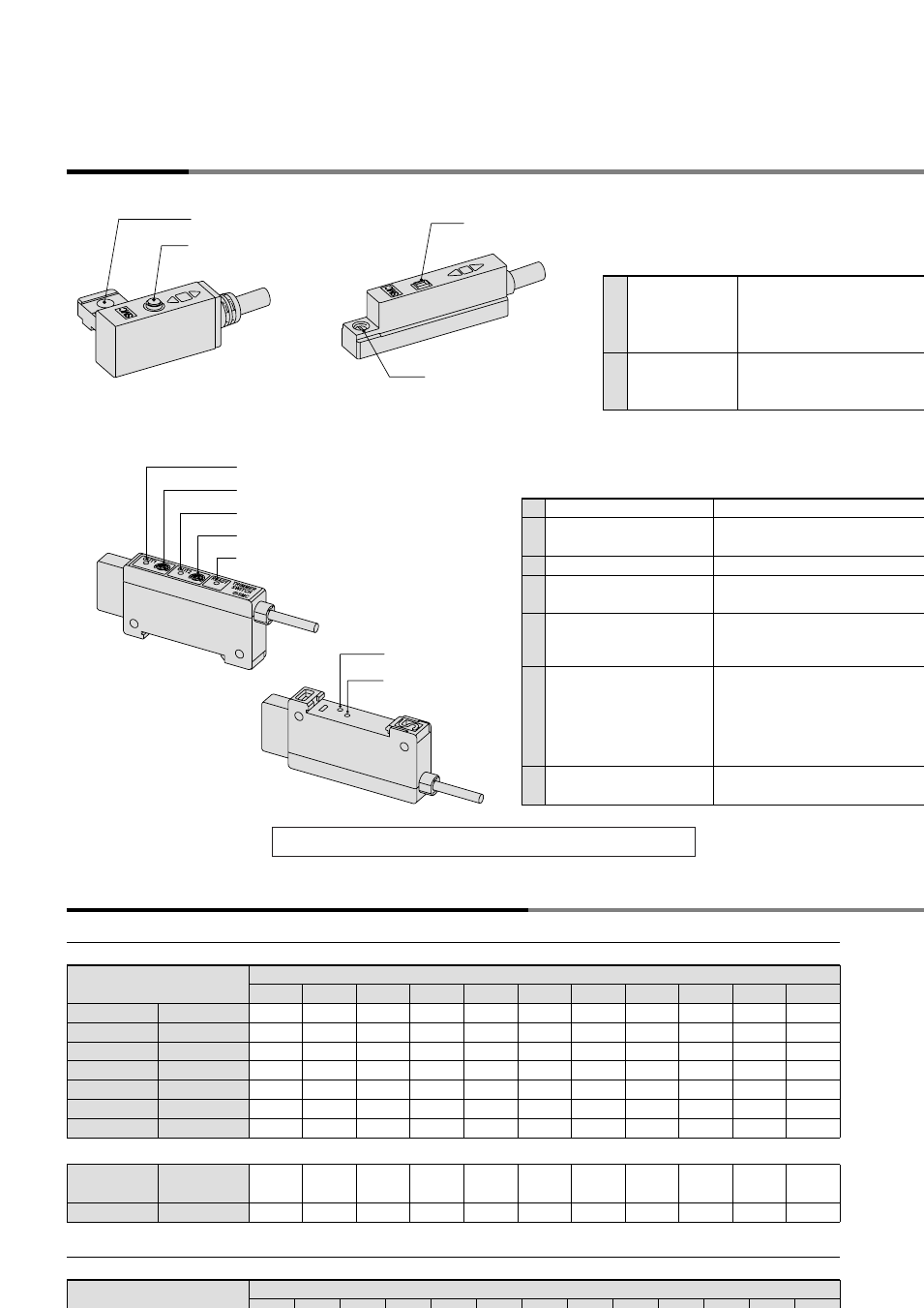
Trimmer Auto Switch
D-
२
7K/D-R
२
K
Descriptions
Sensor unit
Amplifier unit
Applicable actuator and operation range (angle)
Sensor unit D-Y7K
Air gripper
Sensor unit
D-F7K
Air cylinder
Air cylinder
Amplifier unit
1
Output (OUT1) indication: green Lights up when OUT1 outputs.
3
Output (OUT2) indication: orange
OUT1 adjusting trimmer
Lights up when OUT2 outputs.
2
Adjusts the output range of OUT1 when
sensor unit detects the magnetic field.
OUT2 adjusting trimmer
4
Adjusts the output range of OUT2 when
sensor unit detects the magnetic field.
Confirmation of detection at
sensor unit (READY): red
5
Lights up when sensor unit is detecting th
magnetic field. While its lighting, output
ranges of OUT1 and OUT2 are adjustable
7
Confirmation of offset
adjustment (OFFSET): red
Lights up when offset adjustment is
completed.
Offset adjusting trimmer
(ADJ)
6
Adjusts the sensor unit at the time of connectio
Once adjusts, no need to re-adjust as lon
as the sensor unit is not replaced.
Adjustment must be undertaken while the
sensor unit is removed from the actuator.
Refer to the operation manual for details.
Sensor unit
1
Indicator light
Red light turns ON when sensor detects
the magnet field. Green light is ON durin
the suitable position to detect the magne
field (including most sensitive position).
ø3.2 mounting hole
M2.5 x 4L slotted
set screw
Fixes the sensor to the actuator.
2
D-F7K
D-R
२
K
6
7
2
1
D-Y7K
2
1
Parallel gripper
Wide opening
Parallel gripper
Parallel gripper
Parallel gripper
Angular gripper
180
°
opening/closing
MHZ2
MHL2
MHS2 (2 finger)
MHS3 (3 finger)
MHS4 (4 finger)
MHC2
MHW2
10
4
6.8
—
—
—
30
°
to –10
°
—
—
—
—
—
—
—
—
5
8
—
—
—
30
°
to –10
°
—
7
8.5
—
—
—
30
°
to –10
°
88
°
to –5
°
7
10.5
—
—
—
22.5
°
to –10
°
54
°
to –6
°
8
11
6.5
6.5
6.5
—
58
°
to –5
°
8.5
12.5
7
7
7
—
41
°
to –5
°
—
—
7.5
7.5
7.5
—
30
°
to –4
°
—
—
8.5
8
8.5
—
—
—
—
—
—
—
—
—
12
16
20
25
32
40
50
63
—
—
—
—
—
—
—
80
100
12
16
20
25
32
40
50
63
80
100
125
140
160
Compact
guide cylinder
Air cylinder
MGP
—
—
3.5
—
5
—
4.5
—
4.5
—
5.5
—
5.5
4
5.5
4
5.5
6
5.5
6
6
6
The operating ranges are provided as guidelines including the hysteresis and are n
guaranteed value. Consult SMC for alternative actuators than those shown below
CA2
Model
Bore size (mm)
(mm or
°
)
(mm)
Model
Bore size (mm)
Refer to the operation manual for how to adjust/set.
1
2
3
5
4