15 fan headers, Serial ports, Extra usb headers – SUPER MICRO Computer Dual Processor AS 1020C-3 User Manual
Page 49: Chassis intrusion
Chapter 5: Advanced Serverboard Setup
5-15
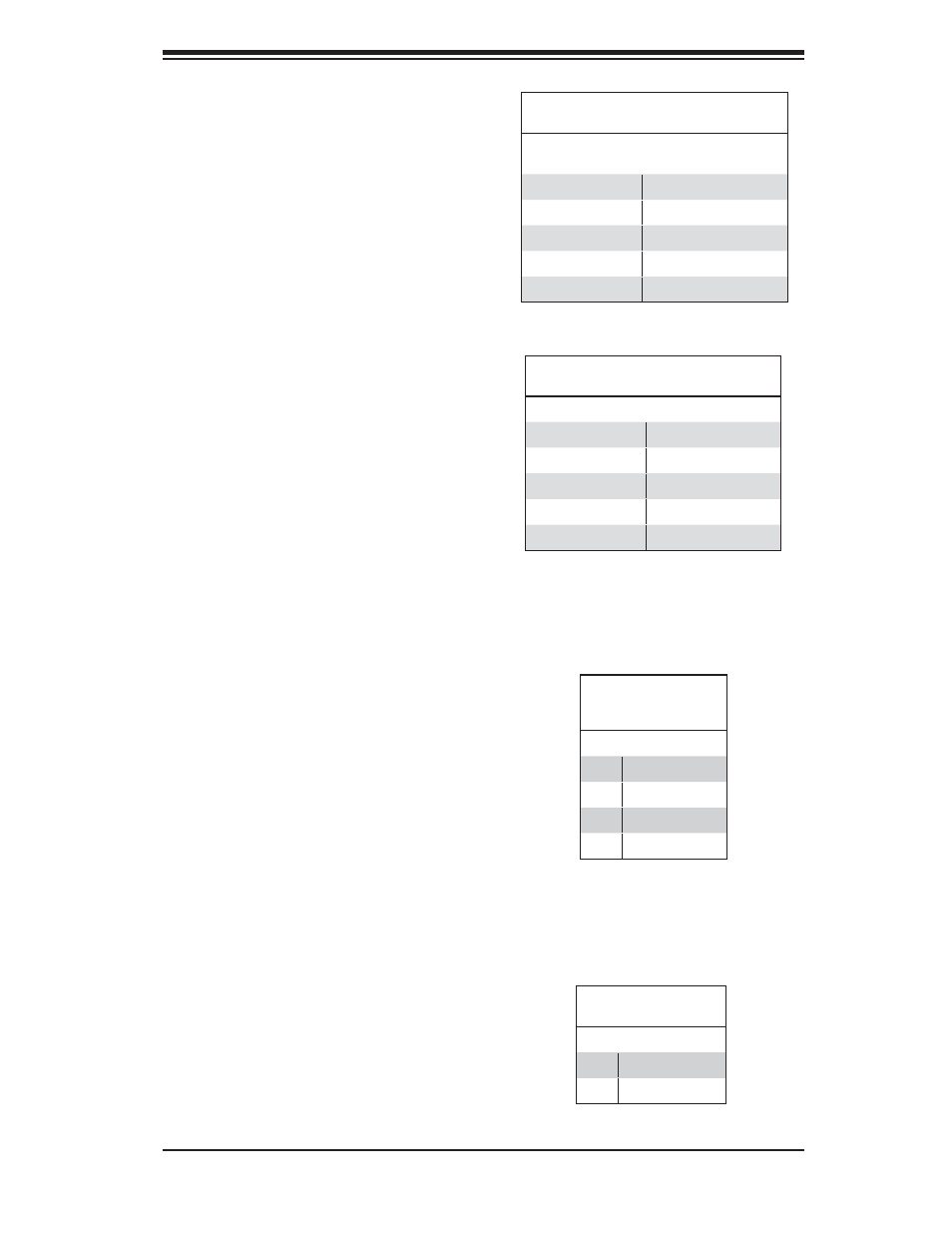
Fan Headers
The H8DCR-3/H8DR-i has fi ve fan
headers, which are designated FAN1
through FAN5. Fans are Pulse Width
Modulated (PWM) and their speed is
controlled via Thermal Management
with a BIOS setting. See the table on
the right for pin defi nitions.
Serial Ports
The COM1 serial port is located be-
side the USB ports and the COM2
header is located by the IDE#1 con-
nector. Refer to the table on the right
for pin defi nitions.
Fan Header
Pin Defi nitions
(FAN1-8)
Pin# Defi nition
1
Ground (Black)
2
+12V (Red)
3
Tachometer
4
PWM Control
Extra USB Headers
Tw o a d d i t i o n a l U S B 2 . 0 h e a d -
ers (USB2/3) are included on the
serverboard. These may be con-
nected to provide front side access.
A USB cable (not included) is needed
for the connection. See the table on
the right for pin defi nitions.
Extra Universal Serial Bus Headers
Pin Defi nitions (JUSB2)
USB2
Pin # Defi nition
USB3/4
Pin # Defi nition
1
+5V
1
+5V
2
PO-
2
PO-
3
PO+
3
PO+
4
Ground
4
Ground
5
Key
5
No connection
Chassis Intrusion
A Chassis Intrusion header is located
at JL1. Attach the appropriate cable
to inform you of a chassis intrusion.
Chassis Intrusion
Pin Defi nitions (JL1)
Pin# Defi nition
1
Battery voltage
2
Intrusion signal
Note: Pin 10 is included on the header but not on
the port. NC indicates no connection.
Serial Port Pin Defi nitions
(COM1, COM2)
Pin # Defi nition
Pin # Defi nition
1
DCD
6
DSR
2
RXD
7
RTS
3
TXD
8
CTS
4
DTR
9
RI
5
Ground
10
NC