Ntrepi – Slant/Fin INTREPID Oil-Fired Boilers User Manual
Page 8
*
Add Suffix: (P)Packaged water boiler less tankless heater, (PT)Packaged water boiler with tankless heater, (PPT)Packaged water boiler with provision for tankless heater, (PZ)Packaged steam boiler less
tankless heater, (PZT)Packaged steam boiler with tankless heater.
†
Ratings apply to the use of light oil at 140,000 Btu per gallon, and a .02% draft (negative pressure) over the fire.
‡
The net I=B=R output ratings shown are based on an allowance for piping and pickup of 1.15 (water) or 1.33 (steam). D.O.E. capacity gross output is divided by the allowance to obtain net rating.
The manufacturer should be consulted before selecting a boiler for unusual piping and pickup requirements such as intermittent system operation, extensive piping, etc.
§
Nominal clay tile liner dimensions.
** Tankless heater rating based on intermittent draw.
¶
Water boiler models TR-30, TR-40, TR-50, TR-60 and TR-70 have two firing rates. The boiler is factory shipped at the lower firing rate. To obtain the higher firing rate, refer to the Intrepid boiler installation
instructions for the appropriate field adjustments.
#
I.B.R. gross output
∆ Collar is oblong, will fit 6" diameter nominal
connector.
NOTE: All boilers under 300,000 Btuh input are
tested and rated for capacity under the U.S.
Department of Energy (D.O.E.) Test Procedures
for Boilers.
©Slant/Fin Corp. 2004. Printed in the U.S.A. 604. Publication No. TR-10.
SLANT/FIN CORPORATION, Greenvale, NY 11548 • Phone: (516) 484-2600
FAX: (516) 484-5921 • In Canada: Slant/Fin LTD/LTEE, Mississauga, Ontario
www.slantfin.com
I
NTREPI
D
11B
11A
10
12
5A
5B
7
13
14 (Rear)
13
6
9
15
8
14 (Rear)
Front view STEAM
Front view WATER
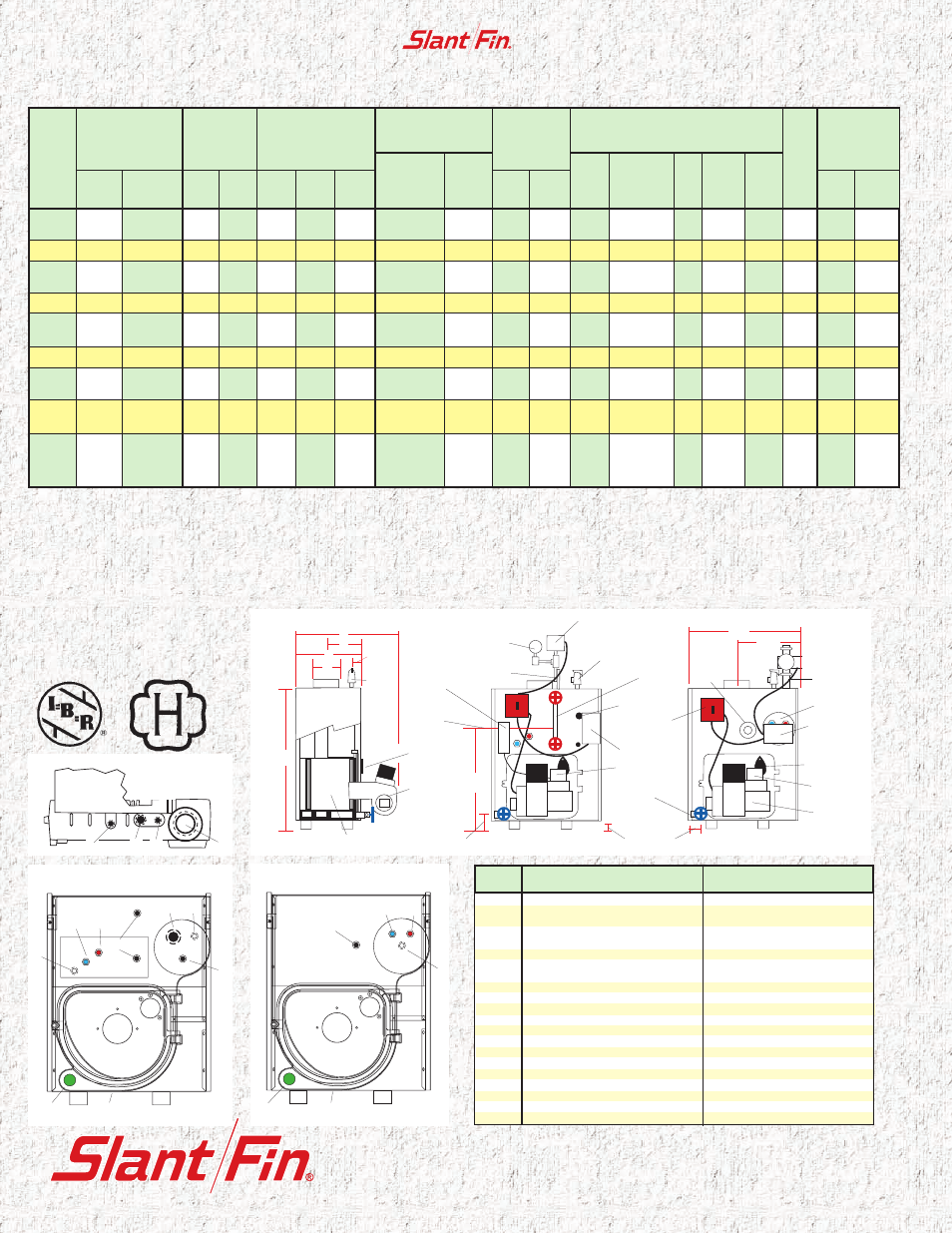
Tapping
Location
STEAM BOILER
WATER BOILER
1
3" supply
1
1
⁄
2
" supply
1A
2" supply tapping (rear section
of L-50, L-60 & L-70 models only)
—
2
Second
1
⁄
4
" siphon, pressure gauge
& pressure cut-out
3
⁄
4
" air vent or expansion tank
3
3
⁄
4
" steam safety valve
3
⁄
4
" water relief valve
4
1
⁄
4
" siphon, pressure gauge
& pressure cut-out
—
5A
—
1
⁄
2
" tankless inlet
5B
—
1
⁄
2
" tankless outlet
6
—
1
⁄
4
" pressure temp. gauge
7
—
1
⁄
2
" hi limit, hi/lo or comb. control
8
3
⁄
4
" low water cut-off, alternate
—
9
1
1
⁄
2
" skimmer tapping
—
10
1
⁄
2
" low limit for tankless
—
11A
1
⁄
2
" tankless inlet
—
11B
1
⁄
2
" tankless outlet
—
12
1
⁄
2
" steam gauge glass & 67 LWCO
—
13
1
1
⁄
2
" return &
3
⁄
4
" drain cock
1
1
⁄
2
" return &
3
⁄
4
" drain cock
14
1
1
⁄
2
" condensate return
1
1
⁄
2
" alternate return
15
3
⁄
4
" zone tapping
—
Top view (Front section)
E
B
A
C
4"
A.S.M.E.
Relief
valve
Burner
Observation
port
Combustion Chamber
Left End—WATER & STEAM
Front—STEAM BOILER
Front—WATER BOILER
Supply
14
5
⁄
8
"
25"
Combination
gauge
Tankless
heater
High/Lo limit
or combination
control for “P”
or “PT” boiler
Observation
Port
LWCO
TR-20
0.75
105,000
91
—
79
—
—
8 x 8 x 15
5 x 15
83.50
—
11
1
⁄
2
8
9
⁄
32
6
∆
1
1
⁄
4
24
1
⁄
4
2
2.20
—
TR-30H
1.00
140,000
121
—
105
—
—
8 x 8 x 15
6 x 15
86.00
—
14
7
⁄
8
10
1
⁄
32
6
1
1
⁄
4
27
5
⁄
8
3
3.00
—
TR-30
¶
1.10
154,000
134
134
117
101
421
8 x 8 x 15
6 x 15
84.85
84.15
14
7
⁄
8
10
1
⁄
32
6
1
1
⁄
4
27
5
⁄
8
3
3.20
3.00
1.25
175,000
151
—
131
—
—
8 x 8 x 15
6 x 15
83.50
—
14
7
⁄
8
10
1
⁄
32
6
1
1
⁄
4
27
5
⁄
8
3
3.40
—
TR-40H
1.50
210,000
182
179
158
134
558
8 x 8 x 15
6 x 15
86.00
84.00
18
1
⁄
4
11
23
⁄
32
7
1
1
⁄
4
31
4
3.80
3.40
TR-40
¶
1.60
224,000
195
195
170
146
608
8 x 8 x 15
7 x 15
84.45
83.80
18
1
⁄
4
11
23
⁄
32
7
1
1
⁄
4
31
4
3.90
3.50
1.80
252,000
218
—
190
—
—
8 x 8 x 15
7 x 15
83.33
—
18
1
⁄
4
11
23
⁄
32
7
1
1
⁄
4
31
4
4.15
—
TR-50H
2.00
280,000
243
239
211
179
746
8 x 8 x 15
7 x 15
86.00
84.00
21
5
⁄
8
13
13
⁄
32
8
1
1
⁄
2
34
3
⁄
8
5
4.40
3.90
TR-50
¶
2.10
294,000
256
255
223
191
796
8 x 8 x 15
8 x 15
84.06
83.45
21
5
⁄
8
13
13
⁄
32
8
1
1
⁄
2
34
3
⁄
8
5
4.40
4.00
2.35
329,000
272
#
—
237
—
—
8 x 12 x 15
8 x 15
—
—
21
5
⁄
8
13
13
⁄
32
8
1
1
⁄
2
34
3
⁄
8
5
4.70
—
TR-60
¶
2.60
364,000
298
#
298
#
259
224
933
8 x 12 x 15
10 x 15
—
—
25
15
3
⁄
32
8
1
1
⁄
2
37
3
⁄
4
6
4.90
4.50
2.85
399,000
327
#
—
284
—
—
8 x 12 x 15
10 x 15
—
—
25
15
3
⁄
32
8
1
1
⁄
2
37
3
⁄
4
6
5.20
—
TR-70
¶
3.10
434,000
352
#
354
#
306
266
1108
8 x 12 x 15
10 x 15
—
—
28
3
⁄
8
16
25
⁄
32
9
—
41
1
⁄
8
7
5.45
5.00
3.35
469,000
381
#
—
331
—
—
8 x 12 x 15
10 x 15
—
—
28
3
⁄
8
16
25
⁄
32
9
—
41
1
⁄
8
7
5.70
—
Boiler
Model
No.
I=B=R Burner
Capacity
Oil Input
GPH
†
BTUH
D.O.E.
Heating
Capacity
MBH
Water Steam
I=B=R Burner
Net Ratings
Water
MBH
‡
Steam
MBH
‡
Steam
Sq. Ft.
I=B=R Chimney Size
Nom. Rect.
x Height
§
(in x in x ft)
I.D.Round
x Height
(in x ft)
A.F.U.E.
%
Water Steam
Dimensions (inches)
Boiler
Length
“A”
Front to
Flue ¢
“B”
Flue
Dia.
“C”
Return
Circulator
Flange
“D”
Overall
Length
“E”
Boiler
section
Tankless
Heater
GPM
**
Water
Steam
POP
safety
valve
Primary
control
Gauge glass
Gauge
Pressure
cut-out
control
Burner
25
1
⁄
2
"
Water
line
Siphon
1
1
⁄
2
"
skimmer
tapping
Primary
control
Burner
Drain
cock and
alternate
tapping
3
3
⁄
4
"
1
3
⁄
4
"
3
1
⁄
2
"
3
2
1
4
Flue
collector
31
7
⁄
8
"
Service
switch
Tankless
limit
control
World class cast-iron oil-fired boilers
®