Page 35, J4 f1 – Jacuzzi J-280 User Manual
Page 39
page 35
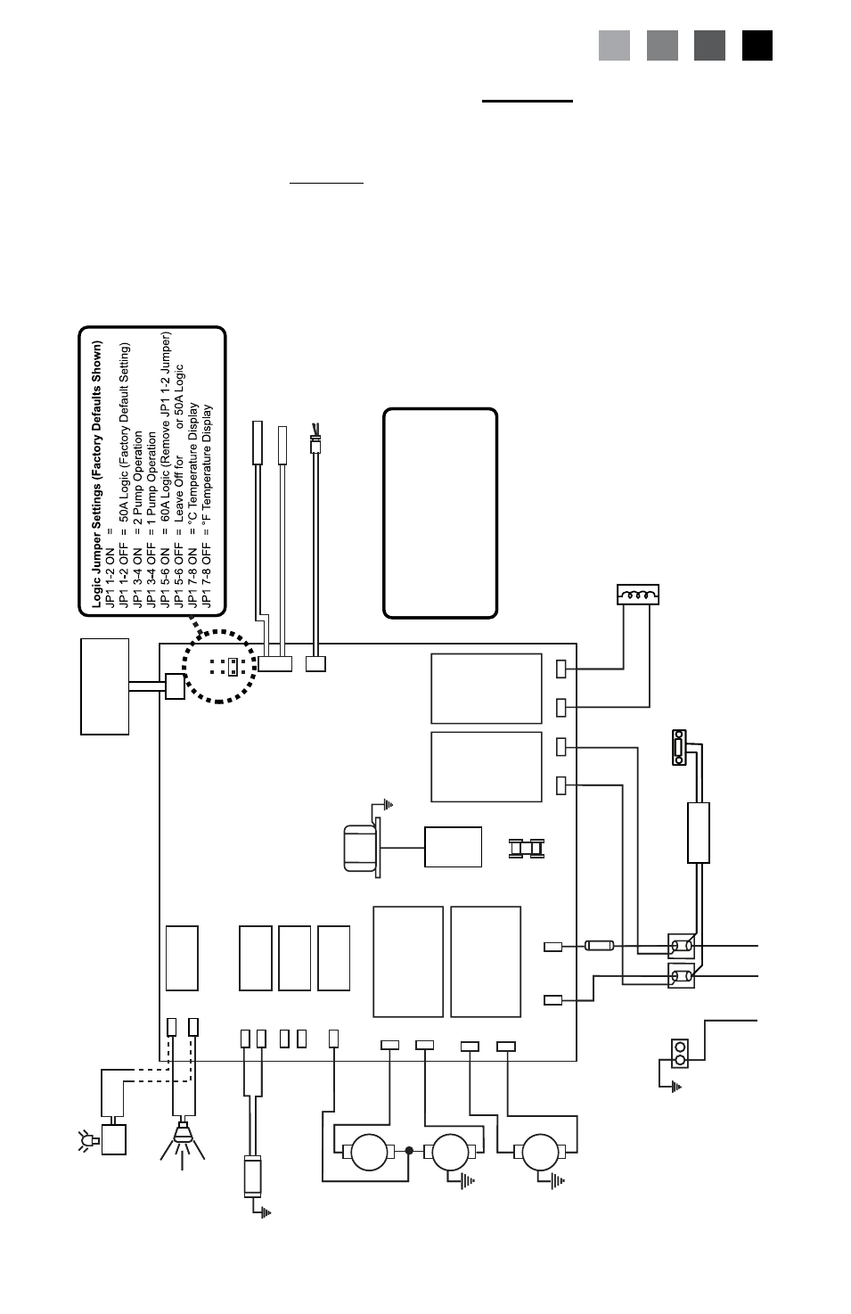
15.0 Circuit Diagram For Models without Circulation
Pump Option
This wiring diagram is used for all J-270 and J-280 240V 60Hz North
American spa models without the Circulation Pump
Option
O
Z
O
N
A
T
O
R
(
O
P
T
IO
N
A
L)
O
3
GRN
TB1
Standard 240 V
AC, 3-Wire Connection (60Hz, 1-Phase Service)
USE COPPER CONDUCT
ORS ONL
Y.
WIRE SIZE MUST
BE
APPROPRIA
TE PER NEC
AND/OR LOCAL
CODES
RED
RED
J6
BLK
J5
WHT
WHT
RED
BLK
BLK
WHT
BLK
RED
RED
BLK
BLK
BLK
2
1
FLOW SWITCH
HI - LIMIT
/ FREEZE SENSOR
TEMPERA
TURE SENSOR
J1
J2
J3
F1
30A, 250V
SC-30
P
U
M
P
1
P
U
M
P
2
T
R
A
N
S
F
O
R
M
E
R
24
0
V
A
C
J4
F1
JP1
4
2
3
1
6
5
8
7
7
6
2
4
HI
HI
LO
M
ai
n
C
o
n
tr
o
l P
an
el
J20
K1
K2
K3
K4
K5
K6
K7
K8
J21
J1
1
J12
J13
J14
J15
J16
J17
J18
J19
J7
J8
J9
J10
This device complies with Part 15 of the
FCC rules. Operation is subject to the
following two conditions:
1.
This device may not cause harmful
interference.
2.
This device must accept any inteference
received including interference that may
cause undesired operation.
Heater 5.5 kW 240
V
A
C
40A
Logic
40A
Optional Stereo
P
ower Supply
WHT
BLK
WHT
BLK
Standard
Footwell
Light
Optional
LED Lighting
Sy
st
em
D
C
U
OR
O
Z
O
N
A
T
O
R
(
O
P
T
IO
N
A
L)
O
3
GRN
TB1
Standard 240 V
AC, 3-Wire Connection (60Hz, 1-Phase Service)
USE COPPER CONDUCT
ORS ONL
Y.
WIRE SIZE MUST
BE
APPROPRIA
TE PER NEC
AND/OR LOCAL
CODES
RED
RED
J6
BLK
J5
WHT
WHT
RED
BLK
BLK
WHT
BLK
RED
RED
BLK
BLK
BLK
2
1
FLOW SWITCH
HI - LIMIT
/ FREEZE SENSOR
TEMPERA
TURE SENSOR
J1
J2
J3
F1
30A, 250V
SC-30
P
U
M
P
1
P
U
M
P
2
T
R
A
N
S
F
O
R
M
E
R
24
0
V
A
C
J4
F1
JP1
4
2
3
1
6
5
8
7
7
6
2
4
HI
HI
LO
M
ai
n
C
o
n
tr
o
l P
an
el
J20
K1
K2
K3
K4
K5
K6
K7
K8
J21
J1
1
J12
J13
J14
J15
J16
J17
J18
J19
J7
J8
J9
J10
This device complies with Part 15 of the
FCC rules. Operation is subject to the
following two conditions:
1.
This device may not cause harmful
interference.
2.
This device must accept any inteference
received including interference that may
cause undesired operation.
Heater 5.5 kW 240
V
A
C
40A
Logic
40A
Optional Stereo
P
ower Supply
WHT
BLK
WHT
BLK
Standard
Footwell
Light
Optional
LED Lighting
Sy
st
em
D
C
U
OR