Cv-m40, 2. 6 pin connector (trigger connector) – JAI CV-M40 User Manual
Page 7
CV-M40
7
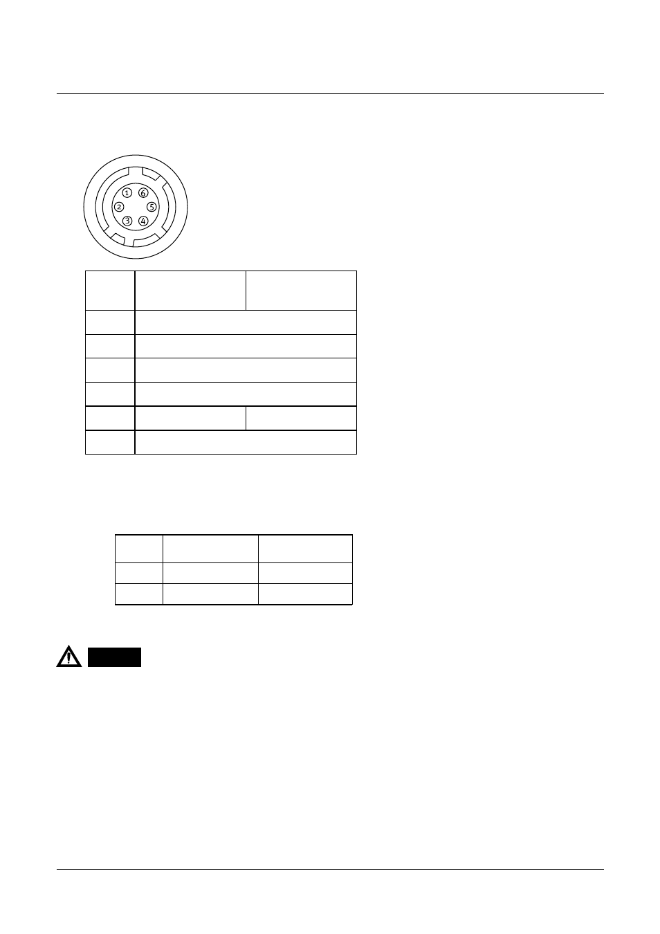
5-2. 6 pin connector (TRIGGER connector)
HR10A-7R-6P (Hirose) male
* Note :
To change the signal output on pin no. 5 and 6, it is necessary to make jumper setting.
See “7-2. Jumpers on board” for more informations.
When trigger signal is input at #5 of 6 pin multi connector, do not input/output HD signal at #6 of 12 pin multi
connector, as it causes a failure in external trigger mode.
1.
Do not input HD or VD signal at pin no.5, when the camera is set at Continuous mode.
2.
Pin no.
HD/VD input or
output
Ext.
trigger/readout
TXD output
RXD input
Ground
Ground
**See note 2.
Ext. trigger input
1
2
3
4
5*
6*
WEN output
Pin no.
Factory pre-set
Others
5
Trigger input
NC
6
WEN output
NC
CAUTION