Pin assignment, Cv-m40, 1. 12 pin connector (dc in/sync connector) – JAI CV-M40 User Manual
Page 6
6
CV-M40
5. Pin assignment
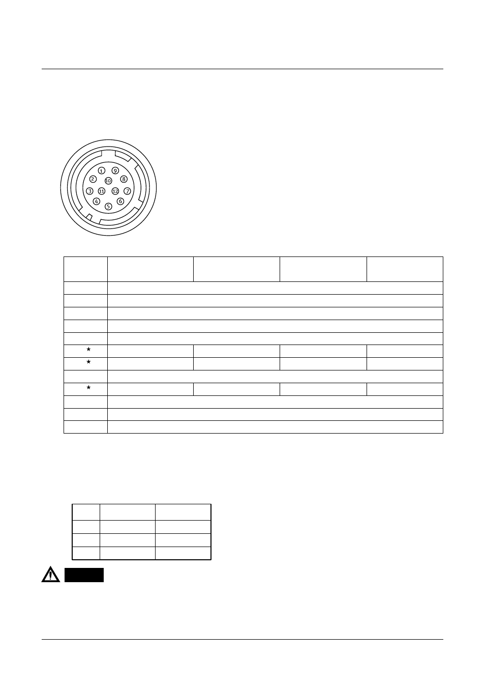
5-1. 12 pin connector (DC IN/SYNC connector)
HR10A-10R-12PB-01 (Hirose) male
* Note : To change the signal output on pin no. 6, 7 and 9, it is necessary to make jumper setting.
See “7-2. Jumpers on board” for more informations.
Pin no. Factory pre-set
Others
6
HD input
HD output
7
VD input
VD output
9
NC
Pixel clock output
When trigger signal is input at #5 of 6 pin multi connector, do not input/output HD signal at #6 of 12 pin multi
connector, as it causes a failure in Ext. trigger mode.
Do not use video output at the same time both from #4 of 12 pin multi connector and BNC connector, as it
causes a failure on video signal due to double termination.
1.
2.
Pin No.
Ext Sync Mode
(Factory setting)
Ext Trigger Mode
H-Reset
Ext Trigger Mode
H Non-reset
Int Sync Mode
GND
DC+12V IN
GND
VIDEO OUT
GND(VIDEO)
Ext.HD IN
Ext.TRIG IN
Ext.HD IN
Int.HD OUT
Ext.VD IN
WEN OUT
Ext.TRIG IN
Int.VD OUT
GND
NC
PLCK/WEN OUT
PLCK/WEN OUT
NC
GND
DC+12C IN
GND
1
2
3
4
5
6
7
8
9
10
11
12
CAUTION