JAI CV-M40 User Manual
Page 18
18
CV-M40
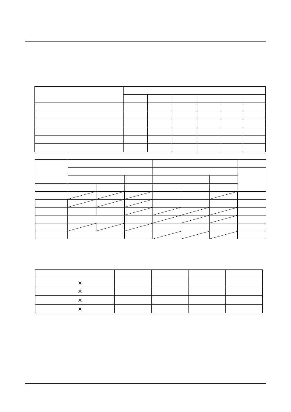
7-2-3. Jumpers on PK8273 board
a) Jumpers JP8 thru JP13 control the input/output state as well as the termination of the HD
and VD signals on pin #6 and #7 of the 12 pin connector.
b) Jumpers JP14 thru JP17 control the effective number of lines in the partial scan mode.
Note : Partial scan is set at 120 (v) as factory pre-set.
I/F Board (PK8273)
Function Mode
JP9
JP12
JP8
JP11
JP13
JP10
Int. Sync
O/S
O/S
O/S
O/S
O/S
O/S
Ext. Sync
S
O
O/S
S
O
O/S
H Reset Trigger (12P)
O
S
-
S
O
O/S
H Non Rest Trigger (12P)
S
O
O/S
S
O
O/S
H Reset trigger (6P)
O
S
-
S
O
O/S
H Non Reset trigger (6P)
S
O
O/S
S
O
O/S
#6
#7
HD signal
VD signal
Pin no. of
12pin
connector
Input
Output
Input
Output
Jumpers
75 ohm
TTL
75 ohm
75 ohm
TTL
75 ohm
#6:input
#7:input
JP8
Short
Open
JP9
Short
Open
JP10
Short
Open
JP11
Short
Open
JP12
Open
Short
JP13
Open
Short
Factory pre-set
Open
Short
Open
Short
Open
Open
30Line 30(V)
648(H)
60Line 60(V)
648(H)
120Line 120(V)
648(H)
240Line 240(V)
648(H)
JP14
Short
Open
Open
Open
JP15
Open
Short
Open
Open
JP16
Open
Open
Short
Open
JP17
Open
Open
Open
Short
Valid period