Output/input set, A pg. 57), Masterpage:right – JVC DR-M150SEK User Manual
Page 57: L-1 output and l-1 input setting
Masterpage:Right+
EN
57
Filename [M150SEK_09Editing.fm]
EDITING
L-1 Output And L-1 Input Setting
The [L-1 IN/OUT] connector accepts and delivers either a composite
signal (regular video signal) or a Y/C signal (a signal in which the
luminance and chrominance signals are separated). Set
AL-1
OUTPUT
B and AL-1 INPUTB to the appropriate mode depending on
the type of appliance connected to the unit’s [L-1 IN/OUT] connector.
1
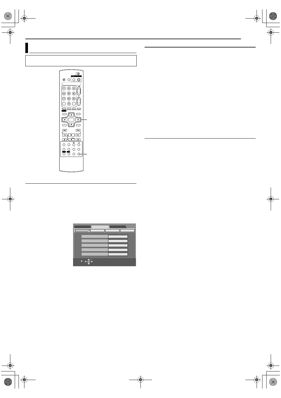
Press SET UP to access the Main Menu screen.
2
Press selection keys to select
AFUNCTION SET UPB, then
press ENTER.
3
Press selection keys
to select
AVIDEO IN/
OUT
B, then press
ENTER.
4
Press selection keys
to select
AL-1
OUTPUT
B or AL-1
INPUT
B, then press
ENTER.
5
Press selection keys
to select the
appropriate setting, then press ENTER.
6
Press SET UP to complete the setting.
\
* The boldface settings below indicate the settings at your purchase.
8
L-1 OUTPUT
^
SCART VIDEO
/ SCART S-VIDEO / SCART
RGB / COMPONENT
SCART VIDEO
:
If a connected appliance’s input is compatible only with regular
video signals, set to
ASCART VIDEOB
.
SCART S-VIDEO:
If a connected appliance’s input is compatible with Y/C signals,
set to
ASCART S-VIDEOB. You can obtain a high-quality picture.
(For connection, be sure to use a 21-pin SCART cable that is
compatible with the Y/C signal.)
SCART RGB:
If a connected appliance’s input is compatible with RGB signals,
set to
ASCART RGBB. You can obtain a high-quality RGB
picture.
COMPONENT:
If a connected appliance’s input is compatible with Y/P
B
/P
R
signals, set to
ACOMPONENTB. You can obtain a high-quality Y/
P
B
/P
R
picture. Switch the TV to the input that you can watch
component video pictures.
8
L-1 INPUT
^
VIDEO
/
S-VIDEO
VIDEO
:
If a connected appliance’s output is compatible only with regular
video signals, set to
AVIDEOB.
S-VIDEO
:
If a connected appliance’s output is compatible with Y/C
signals, set to
AS-VIDEOB. You can obtain a high-quality picture.
(For connection, be sure to use a 21-pin SCART cable that is
compatible with the Y/C signal.)
NOTES:
●
If
AL-1 OUTPUTB is set to ASCART S-VIDEOB or ASCART RGBB, it
is not possible to set
AL-1 INPUTB to AS-VIDEOB.
●
If
AL-2 SELECTB is set to ASAT S-VIDEO/RGBB, it is not possible
to set
AL-1 INPUTB to AS-VIDEOB.
●
Component video signals are not output from the [L-1 IN/OUT]
connector.
●
When Progressive scan mode is engaged, it is not possible to
select the setting of
AL-1 OUTPUTB.
Output/Input Set
●
Turn on the TV and select an input mode such as EXT1.
●
Slide the TV/DVD switch to DVD.
SET UP
(FGDE)
ENTER
Selection Keys
DVD SET UP
FUNCTION SET UP
INITIAL SET UP
VIDEO IN/OUT RECORDING SET
OTHERS
SELECT WITH [CURSORS]
THEN PRESS [ENTER]
MONITOR TYPE
F-1 INPUT
L-1 INPUT
DISPLAY SET
L-1 OUTPUT
L-2 SELECT
16:9AUTO
VIDEO
VIDEO
SCART VIDEO
VIDEO/RGB
EXIT
OK
SELECT
SET UP
M150SEK_00.book Page 57 Wednesday, June 15, 2005 4:04 PM