3 connections, Monitor out, 1 video system connections – JVC BR-DV600UA User Manual
Page 8: 2 audio system connections
12
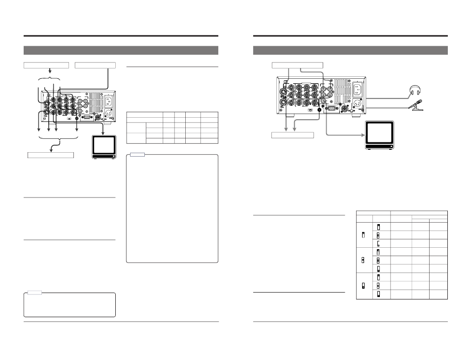
3-1 Video system connections
3 CONNECTIONS
Connecting a monitor
The on-screen display can be viewed on a monitor
connected to the [VIDEO MONITOR OUT] connector.
Connecting video equipment
Connect the video device to the appropriate connector
(4 types are available).
Outputs
5 Analog outputs
Composite signal : [LINE OUT] connector (BNC)
Component signal (Y/B-Y/R-Y) : [COMPONENT OUT]
connectors (BNC x 3)
YC signal : [Y/C OUT] connector (4-pin)
5 Digital output
Digital video signal (conforming to IEEE 1394)
[DV IN/OUT] connector
Inputs
Select input video signals with the front panel’s [VIDEO
INPUT] switch or the No. 108
connector (BNC x 3)
YC signal : [Y/C IN] connector (4-pin)
5 Digital input
Digital video signal
: [DV IN/OUT] connector
(conforming to IEEE 1394)
Reference sync signal
This unit automatically selects the sync signal as shown in
the table below, depending on the presence of external sync
input (SYNC IN) and video input (VIDEO IN), the No. 003
When IEEE 1394 input is selected, “INT” is selected
regardless of the setting. When the No. 108
the operation is the same as that performed with the No.
003
regardless of the setting.
Note:
• When search pictures or low-quality video signals
are input, temporary distortion of picture or sound
may occur. Clean up the signals with a TBC or
other processing device before inputting.
DC 12V
PGZ01945
TIMER
TIME CODE
COMPONENT
VIDEO
SYNC IN
REC
OFF
PLAY
DV
IN/OUT
REMOTE
AUDIO
2
1
SERIAL
CH 1/3
OUT
OUT
IN
IN
B-Y
IN
Y/C
LINE
OUT
OUT
MONITOR
CH 2/4
MONITOR
OUT
R-Y
Y
IN
OUT
Y/C
Input
Y/C
DV
Component
DV
Composite
Composite
Component
Output
Video input to a VCR, etc.
Composite
Monitor TV
External sync signal
Video output from a VCR, etc.
Sync signal generator, etc.
SYNC IN
No
Yes
No
Yes
VIDEO IN
No
No
Yes
Yes
EXTERNAL Playback
INT
EXT
INT
EXT
Recording
INT
INT
VIDEO
VIDEO
AUTO
Playback
INT
EXT
VIDEO
EXT
Recording
INT
INT
VIDEO
VIDEO
INT: Internal sync EXT: External sync VIDEO: Video sync
• The phase of the output signal cannot be adjusted
for external sync signals. The sub carrier cannot be
locked.
• Plugging and unplugging the external sync or video
signal connector during operation causes distortion
in the picture and sound for about 10 seconds.
• When signals input from the composite connector
are output from the component connector, color may
disappear in some parts of the left section of the
monitor screen. This is not a malfunction.
• The set up is not applied to signals input to the
[DV IN/OUT] connector and output in EE mode
(component, Y/C, composite). Input signals are
recorded as is.
• Use a video signal of less than 1 V(p-p) such as a
black burst signal for external sync signal.
• When video signals are input to the DV IN/OUT
connector, distortion may occur in the lower section
of the picture in the EE mode. However, recording
is performed normally.
• When the No. 003
set to “EXTERNAL” and no signal is input to the
[SYNC IN] connector, noise may appear in the
playback picture. This is not a malfunction.
Notes:
13
DC 12V
PGZ01945
TIMER
TIME CODE
COMPONENT
VIDEO
SYNC IN
REC
OFF
PLAY
DV
IN/OUT
REMOTE
AUDIO
2
1
SERIAL
CH 1/3
OUT
OUT
IN
IN
B-Y
IN
Y/C
LINE
OUT
OUT
MONITOR
CH 2/4
MONITOR
OUT
R-Y
Y
IN
OUT
3 CONNECTIONS
Audio output from a VCR, etc.
Audio input to a VCR, etc.
DV
Mic
Headphones
DV
Analog audio
(2 channels)
Analog audio
(monaural)
Analog audio (2 channels)
Connection with a monitor TV
The audio output from the [AUDIO MONITOR OUT] connector
is monaural.
Use the front panel [AUDIO MONITOR] switch or No. 211
੬
See “Playback preparation” on page 28.
Headphones jack
Audio can be monitored in stereo using the headphones.
Use the front panel [AUDIO OUTPUT] switch to select the
audio channels you want to monitor. The selected audio
channel is shown in the table below. Adjust the audio volume
level with the front panel [PHONES] control.
Inputs
5
Analog inputs
Audio connectors (CH1/3, CH2/4)
Analog input connectors are only provided for 2 channels. It is
not possible to record 4 channels simultaneously. Audio input
from each connector is normally recorded on the CH1 and CH2
channels. Recording on the CH3 and CH4 can be performed
in the Audio Dubbing mode with the No. 245
For audio dubbing, refer to “Audio dubbing” on page 27.
5
Digital inputs
Digital signals conforming to IEEE 1394 can be input to the
[DV IN/OUT] connector. In this case, the audio recording level
cannot be adjusted. When audio signals are input to the [DV
IN/OUT] connector, some noise will occur at the point where
recording ends. To reduce this noise during playback, set the
No. 214
5
Mic input jack
Connect a monaural microphone. The same audio is recorded
on both channels.
Outputs
5
Analog outputs
Audio connectors (CH1/3, CH2/4)
Analog output connectors are provided for 2 channels. For
MiniDV format, use the front panel [AUDIO OUTPUT] switch to
select for 4-channel audio. The selected audio channel is
shown in the table below.
੬
See “Playback preparation” on page 28.
5
Digital outputs
Digital signals conforming to IEEE 1394 are output from the
[DV IN/OUT] connector.
Relationship between [AUDIO OUTPUT] / [AUDIO MONITOR]
switch and audio output channel
(During playback with 32 kHz sampling, audio dubbing, and
DV input with the 32 kHz sampling in the EE mode)
Regardless of setting of this switch, CH1/2 is selected for
ordinary recording, record pause and analog audio input in the
EE mode. CH3/4 is selected for audio dubbing in the Pause
mode.
With the No. 054
“AUDIO”.
Monitor TV
CH1
CH1
CH2
CH1/3
CH1/3
CH2/4
CH3
CH3
CH4
CH1/2
CH1
CH2
CH1/2/3/4
CH1/3
CH2/4
CH3/4
CH3
CH4
CH2
CH1
CH2
CH2/4
CH1/3
CH2/4
CH4
CH3
CH4
R
L
MIX
CH1/2
MIX
CH3/4
CH1/2
MIX
CH3/4
CH1/2
MIX
CH3/4
AUDIO switch
Connector
MONITOR
OUTPUT
MONITOR OUT
AUDIO OUT
CH1/3
CH2/4
3-2 Audio system connections