4 menu switches, 3 connections, 1 menu switch organization – JVC BR-DV600UA User Manual
Page 11
18
3 CONNECTIONS
5 Control via the DV connector
• When the DV connector is used for control, assemble editing cannot be performed.
• When the VCR is stopped via the DV connector, a command error message may be returned to the controller. This is not
a malfunction.
5 Cable connection to the [DV IN/OUT] connector
Set the video input to “DV IN” or “IEEE 1394” using either the switch on the front panel or the No. 108
੬
See “Recording preparation” on page 26.
* If you switch the video input when the DV connection is active, turn this unit off and on again after changing the setting.
Menu switch settings
• When controlled by another device via the [DV INPUT] connector
Set the No. 050
and “JVC BUS + RS422A + IEEE 1394”.
• To record the master tape’s time code with the DV-to-DV connection, set the No. 460
to “ON”. (
੬
See “Time code recording” on page 33.)
Notes:
• Connect the cable after the menu switches have been set and the connected equipment is turned ON. (When the
BR-DV600UA/EAs are connected to each other, it is not necessary to turn the power ON.)
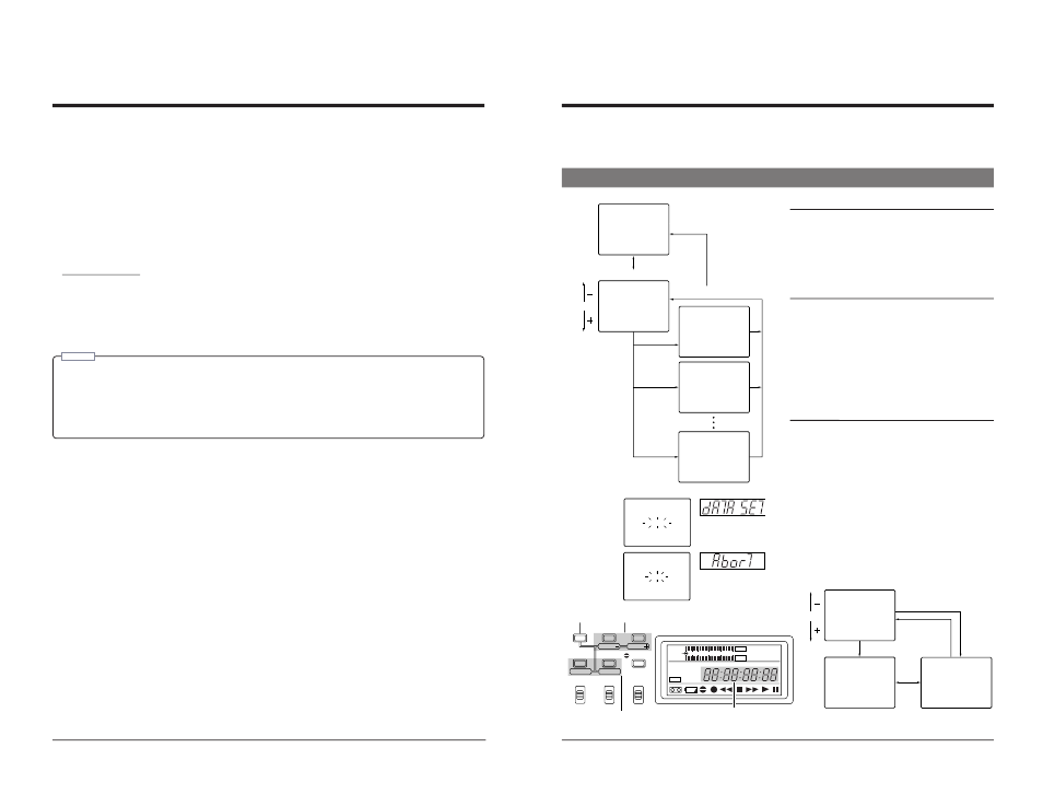
• To record the playback VCR’s user bits, use the BR-DV600UA/EA as a player. DROP> menu switch for the tape in the player VCR. (U MODEL) • When this unit is used with the No. 460 [TIME CODE OUT] connector. 19 4 MENU SWITCHES You can set menu switches using either the on-screen display or the counter display. To set switches on the on-screen display, Menu switch group 0 3 : SYNC SE L ECT 5 0 : REMOTE SE L ECT 0 0 OF F 0 2 : OPERAT I ON LOCK 0 STOP TCR 1 2 : 0 0 : 0 0 : 0 0 0 0 ~ : SYSTEM 0 0 ~ : T I ME CODE 0 0 ~ : ONSCREEN M : HOUR METER 3 0 0 ~ : AUD I O 2 0 0 ~ : SERVO / SYSTEM 0 0 0 ~ : V I DEO 1 [SELECT] [MENU] [SET] [MENU] [SHIFT] U A US +RS 4 2 TO 2 A J VC B 4-1 Menu switch organization Menu switch group select screen Pressing the [MENU] button with the normal screen Menu switch setting screen To access this screen, press the [SELECT] button on the Menu switch group select screen Menu switch setting screen On-screen display L I NE 0 8 : V I DEO I NPUT SE L ECT 1 Y / C 0 9 : V I DEO I NPUT 2 1 ON 2 5 : SET UP 1 0 3 : SYNC SE L ECT U A 5 0 : REMOTE SE L ECT US +RS 4 2 0 0 OF F 0 2 : OPERAT I ON LOCK 0 TO 2 A J VC B 5 2 : STEP S LOEW MODE A R F 5 3 : STOP FUNC. AT SE ST 0 0 M C R A H E OP STOP TCR 1 2 : 0 0 : 0 0 : 0 0 ( HOUR METER ) H : DRUM HOUR METER 0 0 0 0 0 D 0H 0 0 : SYSTEM 0 0 : T I ME CODE 0 0 : ONSCREEN M : HOUR METER 3 0 0 : AUD I O 2 0 0 : SERVO / SYSTEM 0 0 0 : V I DEO 1 [SET] [MENU] [SHIFT] [SELECT] [MENU] Menu switch setting screen On-screen display Switching the [SHIFT] +/–: Item select SELECT: Changes the setting. Enters the setting. Menu switch display SHIFT SET SELECT SHIFT MENU HOLD SHIFT A. DUB ADVANCE PRESET MENU OVER OVER H M S F AUD LOCK 32k 48k PB NDF SERVO RF DEW AUTO OFF HOLD CH 2/4 CH 1/3 dB 40 30 20 10 0 V.IN/A.MONI A.OUT COUNTER DV CTL TC CH-1/2 CH-3/4 Y/C (CPN) LINE L R MIX MIX D A T A S E T A B O R T Counter display When entered When data has not Menu switch setting procedure 1 Press the [SHIFT –/+] button on the menu switch setting screen to select the menu switch you want to The selected menu switch number blinks. 2 Press the [SELECT] button to change the set value. [ The set value is entered and the normal screen is To access another group menu switch setting screen without
• When this unit is used with the No. 460
you will need to connect a monitor to the VCR’s [VIDEO MONITOR OUT] connector. This section explains how to set switches
using the on-screen display. The same procedures apply to switch setting on the counter display, the only difference being that
each menu switch item is indicated by numeric code rather than by name.
select screen
4
5
H
displayed brings up the menu switch group select screen.
Select the desired group with the [SHIFT +/–] button.
The selected group number blinks.
Press the [SELECT] button to go to the selected group
menu switch setting screen.
menu switch group select screen.
Press the [MENU] button to go to the menu switch group
select screen.
4
5
H
setting screen
SET:
UB
been entered yet
set.
[
3 Repeat steps 1 and 2 to change any other menu switches.
4 Press the [SET] button to end menu switch setting.
restored. When entering the data, the indications
shown on the left are displayed. If data has not been
entered and menu switch setting is ended, “Abort”
indication is shown.
ending menu switch setting, press the [MENU] button.