Controls and features, Rear view, Front view – JVC TM-A101G User Manual
Page 3
TM-A101G
1-3
No.51921
ENGLISH
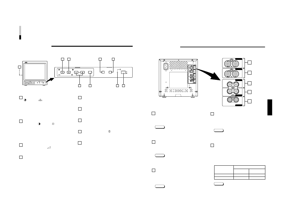
Video A terminals [VIDEO A IN/OUT]
Video signal input (IN) and output (OUT) terminals.
The output terminal is bridge-connected.
IN
: Video signal input terminal
OUT : Bridge-connected video signal output terminal
Notes:
* For corresponding audio signals, use the AUDIO A
terminals
@
.
* Also refer to BASIC CONNECTION EXAMPLE
on page 12.
Video B terminals [VIDEO B IN/OUT]
Video signal input (IN) and output (OUT) terminals.
The output terminal is bridge-connected.
IN
: Video signal input terminal
OUT : Bridge-connected video signal output terminal
Notes:
* For corresponding audio signals, use the AUDIO B
terminals
#
.
* Also refer to BASIC CONNECTION EXAMPLE on
page 12.
Audio A terminals [AUDIO A IN/OUT]
Input (IN) and output (OUT) terminals for the audio signal
corresponding to the VIDEO A terminals
0
.
The output terminal is bridge-connected.
IN
: Audio signal input terminal
OUT : Bridge-connected audio signal output terminal
Notes:
* For corresponding video signals, use the VIDEO A
terminal
0
.
* Also refer to BASIC CONNECTION EXAMPLE
on page 12.
REAR VIEW
10
11
12
13
14
5
VIDEO A
VIDEO B
AUDIO A
AUDIO B
REMOTE
OUT
IN
OUT
IN
OUT
OUT
ASPECT
INPUT
IN
IN
VIDEO A
VIDEO B
AUDIO A
AUDIO B
REMOTE
OUT
IN
OUT
IN
OUT
OUT
ASPECT
INPUT
IN
IN
10
11
12
13
14
Audio B terminals [AUDIO B IN/OUT]
Input (IN) and output (OUT) terminals for the audio
signals corresponding to the VIDEO B terminals
!
.
The output terminal is bridge-connected.
IN
: Audio signal input terminal
OUT : Bridge-connected audio signal output terminal
Notes:
* For corresponding video signals, use the VIDEO B
terminals
!
.
* Also refer to BASIC CONNECTION EXAMPLE
on page 12.
Remote terminals
[REMOTE INPUT, ASPECT]
Remote terminals for external control. Selecting VIDEO A
or VIDEO B and ASPECT RATIO is available via external
control. External control is set in the
screen.
To use external control, you must build a switch cable
and connect it to the REMOTE terminals.
Note:
●
Also refer to BASIC CONNECTION EXAMPLE on
page 12.
External control switch
Open circuit
Closed circuit
(open)
(short)
ASPECT RATIO
4–3 (4:3)
16–9 (16:9)
INPUT
INPUT A
INPUT B
External control
functions
Chroma/Phase button
[
CHROMA/
PHASE]
Press this button to activate the picture color density
adjustment mode or picture hue adjustment mode. Each
time you press the button, the adjustment item changes.
Picture color density
f
Picture hue
Adjust the value with the VOLUME/SELECT buttons
3
.
Also used as a control button in the menu function mode.
Contrast/Brightness button
[CONTRAST
/ BRIGHT
]
Press this button to activate the picture contrast adjust-
ment mode or picture brightness adjustment mode. Each
time you press the button, the adjustment item changes.
Picture contrast
f
Picture brightness
Adjust the value with the VOLUME/SELECT buttons
3
.
Also used as a control button in the menu function mode.
Volume/Select buttons
[VOLUME/SELECT –
+]
Adjusts the speaker volume. Also used as a control
button in the menu function mode.
Menu button [MENU]
Displays and disappears the