Jumper table, Cv- m 77, 2 jumper table – JAI CV-M77 User Manual
Page 22: Jumper settings versus connector pin configuration, Pin hirose connector, Pin dsub connector
CV-
M
77
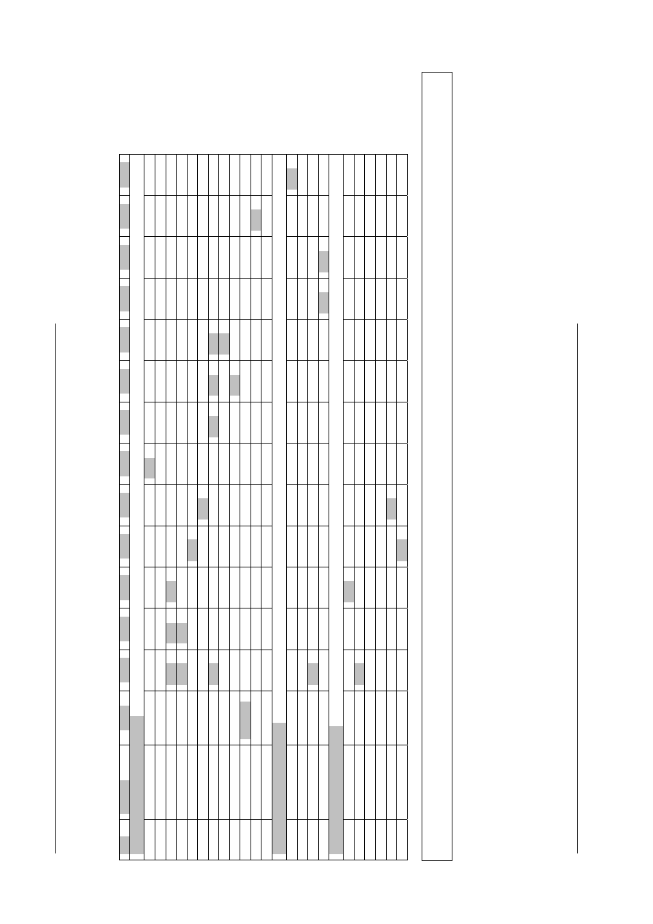
9.2 Jumper
table
Jumper settings versus
connector pin configuration.
Pin#
Function
JP301
JP302
JP303
JP304
JP305
JP306
JP307
JP308
JP309
JP310
JP311
JP312
JP401
JP402
12-pin Hirose connector
6
Ext. HD input
S
ho
rt
6
Int.
H
D
outp
ut
S
ho
rt
7
Ext. VD input
Open
Short
O
pe
n
7
Ext. VD outp
ut
Open
S
ho
rt
9
N
C
O
pe
n
9
P
C
LK
o
ut
pu
t
S
ho
rt
O
pe
n
10
W
E
N
O
pe
n
Short
Short
O
pe
n
10
N
C
O
pe
n
O
pe
n
10
G
N
D
O
pe
n
S
ho
rt
S
ho
rt
11
T
rig
ge
r
C
ap
ac
ito
r
11
N
C
O
pe
n
O
pe
n
11
*)
+
12
V
D
C
O
pe
n
S
ho
rt
6-pin Hirose connector
4
N
C
Open
S
6
W
E
N
O
pe
n
S
ho
rt
O
pe
n
6
E
E
N
Open
S
ho
rt
9-pin DSUB connector
1
N
C
O
pe
n
1
V
D
in
pu
t
O
pe
n
O
pe
n
S
ho
rt
6
H
D
in
pu
t
O
pe
n
6
H
D
o
ut
pu
t
O
pe
n
9
N
C
O
pe
n
9
P
C
LK
o
ut
pu
t
O
pe
n
S
ho
rt
4
G
N
D
ho
rt
NOTE: Whe
n
using the HD/VD, PCLK and WEN signals (input or output) from the 12 pin connector do not use the same signals (input
or output) from the 9 pin D-SUB c
onnector and vice versa.
*) The ext
ernal trigger
pulse or DC +12V can be input at pi
n No.11 of the 12 pin Hirose connector by changing the jumper set
ting on
PK8308
and PK8309. A capacito
r is mounted at jumper JP301 to avoid feeding
th
e trigger circuit with +12
V
DC. If this capacitor is re
moved from JP301
for some reason make sure JP301 is open befor
e feeding th
e camera with +12V DC
at pin No.11 of the 12 pin Hirose co
nnector.
*) Greyed
out jumper settings are f
actory settin
gs.
- 22 -