0 circuit board diagrams, Dedicated power models (60 hz) – Jacuzzi J - 375 User Manual
Page 46
42
J-300 Series
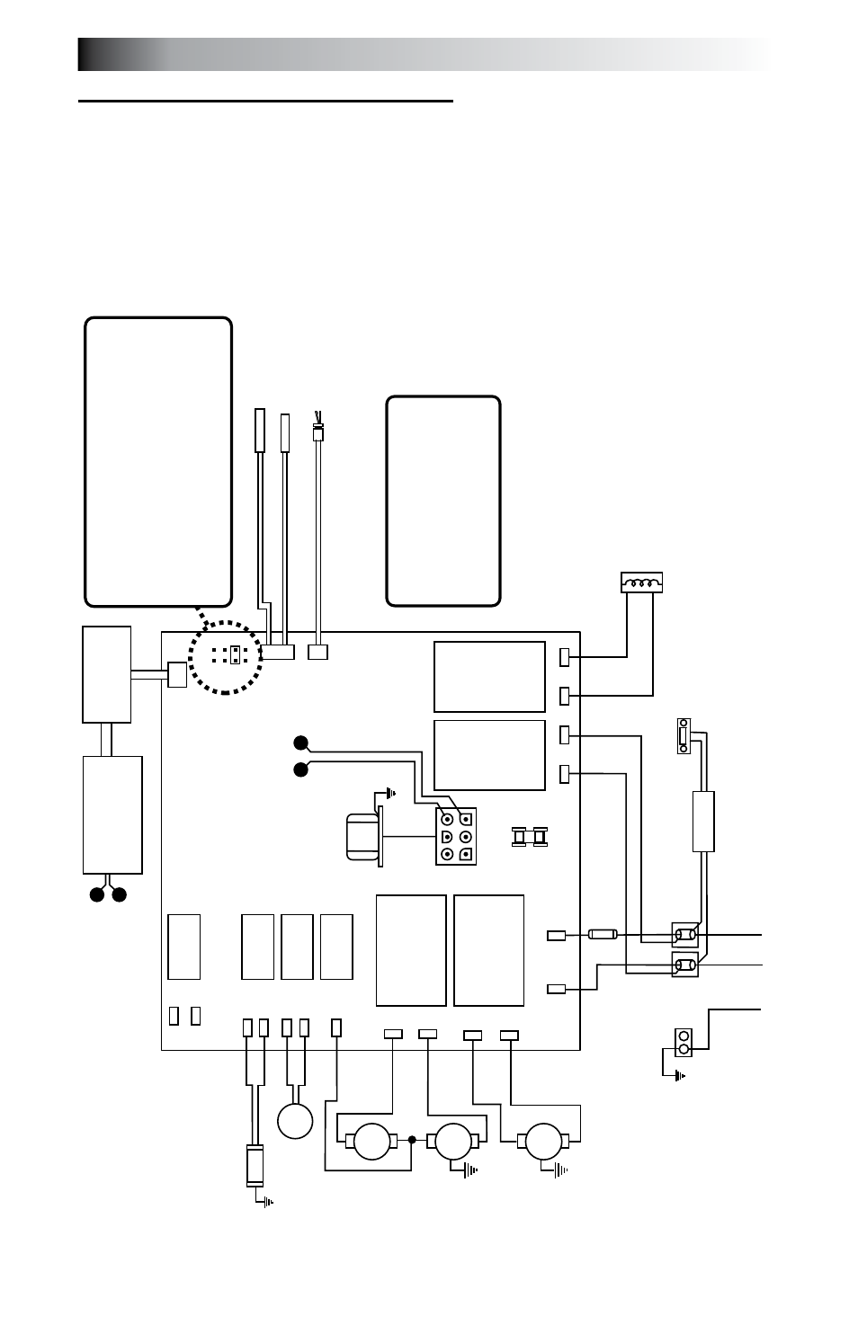
16.0 Circuit Board Diagrams
16.1
north american J-335, J-345, J-355, J-365 and J-375
Dedicated power models (60 Hz)
This wiring diagram is used for all North American, 240V (60 Hz)
dedicated power models.
Optional Stereo
And
Power Supply (not of
fered on J-325 Models)
Power Supply
O
Z
O
N
A
T
O
R
(
O
P
T
IO
N
A
L)
O
3
GRN
TB1
Standard 240 V
AC, 3-W
ire Connection (60Hz, 1-Phase Service)
USE COPPER CONDUCT
ORS ONL
Y. WIRE SIZE MUST
BE
APPROPRIA
TE PER NEC
AND/OR LOCAL
CODES
RED
RED
J6
BLK
J5
WHT
WHT
WHT
RED
BLK
BLK
BLK
WHT
BLK
RED
RED
BLK
BLK
BLK
2
1
FLOW SWITCH
HI - LIMIT
/ FREEZE SENSOR
TEMPERA
TURE SENSOR
J1
J2
J3
F1
30A, 250V
SC-30
P
U
M
P
1
P
U
M
P
2
T
R
A
N
S
F
O
R
M
E
R
24
0
V
A
C
F1
JP1
4
2
3
1
6
5
8
7
7
6
2
4
HI
HI
LO
C
C
o
n
tr
o
l P
an
el
J4
CIRC.
PUMP
J20
K1
K2
K3
K4
K5
K6
K7
K8
J21
J1
1
J12
J13
J14
J15
J16
J17
J18
J19
J7
J8
J9
J10
Logic Jumper Settings (Factory Defaults Shown)
JP1 1-2 ON = 40A
Logic
JP1 1-2 OFF = 50A
Logic (Factory Default Setting)
JP1 3-4 ON = 2 Pump Operation
JP1 3-4 OFF = 1 Pump Operation
JP1 5-6 ON = 60A
Logic (Remove JP1 1-2 Jumper)
JP1 5-6 OFF = Leave Of
f for 40A
or 50A
Logic
JP1 7-8 ON = Celsius
Temperature Display
JP1 7-8 OFF = Fahrenheit
Temperature Display
This device complies with Part 15 of the
FCC rules. Operation is subject to the
following two conditions:
1.
This device may not cause harmful
interference.
2.
This device must accept any inteferenc
e
received including interference that ma
y
cause undesired operation.
Heater 5.5 kW 240 V
AC
J335/J345/J355/J365
W
aterfall Light/
Footwell Light
Controller
X
X
W
W
12V
AC From
Transformer
12V
AC Output to
W
aterfall Light/ Footwell Light Controller
42