2 north american j-315 and j-325 convertible power, Models (60 hz), J-300 series – Jacuzzi J - 375 User Manual
Page 47
43
J-300 series
J-300 Series
16.2
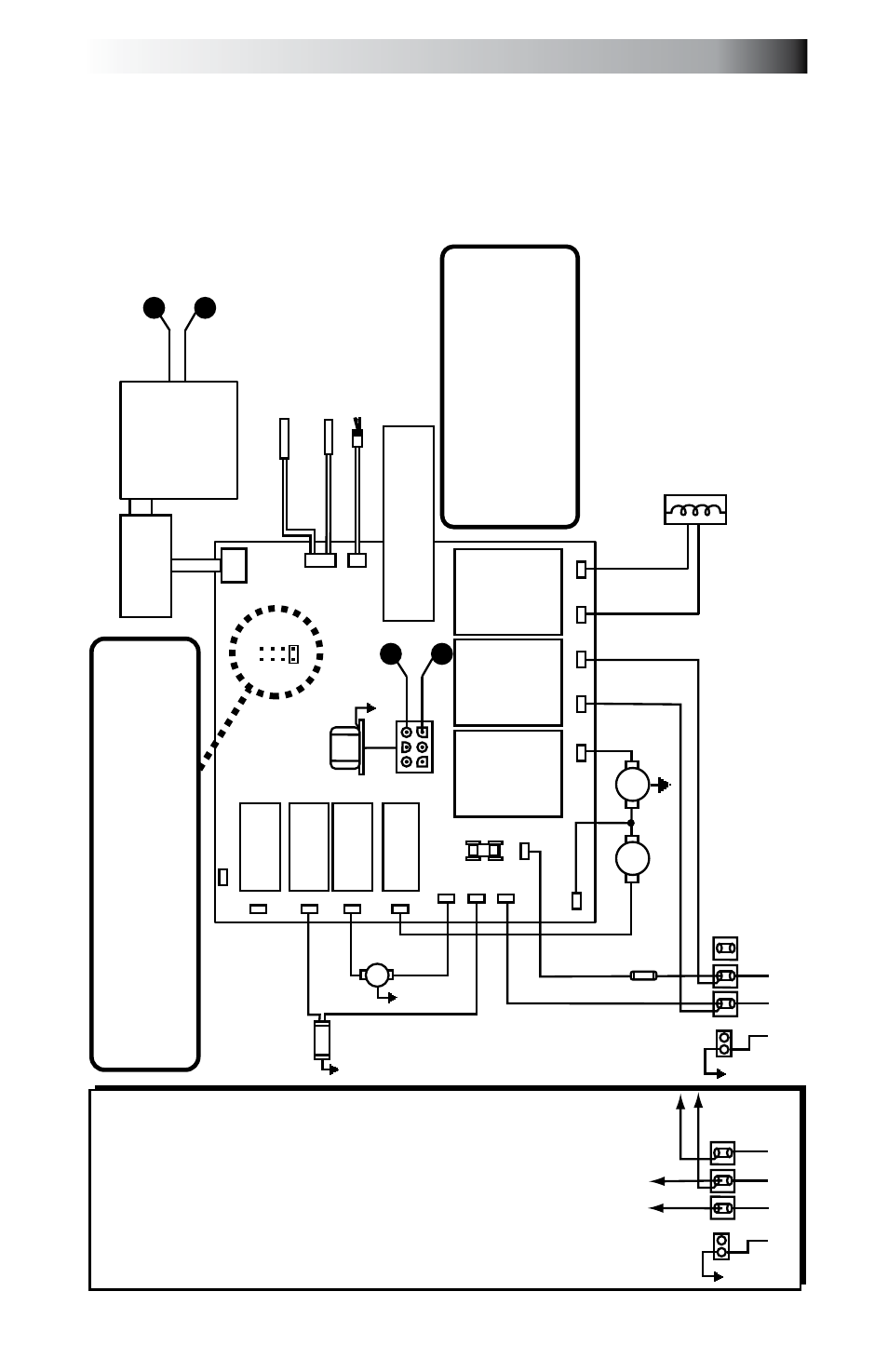
north american J-315 and J-325 Convertible Power Models
(60 Hz)
This wiring diagram is used for all North American 120/240V 60 Hz
convertible power models.
note: Optional 120/240 VAC 4-wire connection enhances heater output
from 1kW to 4kW.
O
zo
na
to
r
(O
pt
io
na
l)
O
3
GRN
TB1
Standard 120 V
AC 3-W
ire Connection
(60 Hz, 1 Phase, 15
A
Service)
Use copper conductors ONL
Y. Wire size must be
appropriate per NEC and/or local codes
(All Canadian spas must be hard wired per CSA)
.
WHT
WHT
WHT
WHT
WHT
BLK
BLK
RED
BLK
BLK
BLK
BLK
BLK
RED
RED
RED
BLK
3
2
1
Heater 1.0 kW @ 120 V
AC
4.0 kW @ 240 V
AC
Flow Switch
Hi-limit/Freeze
Sensor
Temperature Sensor
J2
J3
F1 20A 250V SC-20
C
irc
.
P
um
p
M
ai
n
P
um
p
Tr
an
sf
or
m
er
12
0
V
A
C
J4
BLK
GRN
TB1
WHT
BLK
2
1
O
p
ti
o
n
al
1
20
/2
40
V
A
C
4-
W
ir
e
C
o
n
ve
rt
ib
le
H
ea
te
r
C
o
n
n
ec
ti
o
n
1.
R
em
ov
e
an
d
di
sc
ar
d
th
e
fa
ct
or
y
in
st
al
le
d
G
F
C
I C
or
d
(U
S
o
n
ly
, a
ll
C
an
ad
ia
n
s
p
as
m
u
st
b
e
h
ar
d
w
ir
ed
).
2.
M
ov
e
R
E
D
*
w
ire
fr
om
T
B
1
po
si
tio
n
#1
to
T
B
1
po
si
tio
n
#3
as
s
ho
w
n
be
lo
w
.
3.
P
er
m
an
en
tly
c
on
ne
ct
to
th
e
po
w
er
s
up
pl
y.
Use
copper conductors ONL
Y
.
W
ire size must be
appropriate per NEC and/or
local codes.
4.
I
f h
ot
tu
b
is
to
b
e
op
er
at
ed
on
3
0A
s
er
vi
ce
, m
ak
e
su
re
th
e
ju
m
pe
r
pr
ov
id
ed
a
t
lo
ca
tio
n
JP
1
#1
&
2
on
th
e
ci
rc
ui
t b
oa
rd
is
in
st
al
le
d.
I
f
ho
t t
ub
is
to
b
e
op
er
at
ed
o
n
40
A
s
er
vi
ce
, r
em
ov
e
th
e
ju
m
pe
r
JP
1
#1
&
2
on
th
e
ci
rc
ui
t b
oa
rd
.
HI
LO
JP1
4
2
3
1
6
5
8
7
Logic Jumper Settings (Factory Defaults Shown) JP1 1-2 ON = 15A
Logic (3-wire 120 V
AC operation only)
JP1 1-2 ON = 30A
Logic (4-wire 120/240 V
AC operation only)
JP1 1-2 OFF = 40A
Logic (4-wire 120/240 V
AC operation only)
JP1 7-8 ON = Celsius
Temperature Display
JP1 7-8 OFF = Fahrenheit
Temperature Display
This device complies with Part 15 of the
FCC rules. Operation is subject to the
following two conditions:
1.
This device may not cause harmful
interference.
2.
This device must accept any inteference
received including interference that may
cause undesired operation.
J20
J21
J12
J14
J16
J1
1
J15
J13
J17
J7
J8
J9
J10
J5
J6
Heater IN
Heater OUT
F1*
K
1
K
2
K
3
K
4
K
5
K
7
K
8
J1
C
o
n
tr
o
l
P
an
el
RED
*
RED
3
X
W
J-315/J-325
W
aterfall Light/
Footwell Light
Controller
12V
AC Output to W
aterfall Light/
Footwell Light Controller
X
W
43