How to initialize the setting, Basic connection example – JVC TM-H1900G User Manual
Page 7
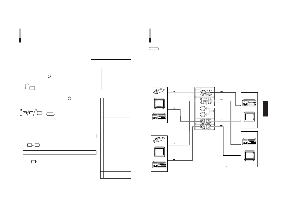
TM-H1900G
1-7
No.51960
12
Functions (Items)
Initialization
(setting)
SHARPNESS
00
ADJ. BAR POSI
LOWER
COLOR TEMP
6500
COLOR SYSTEM
AUTO
RUSH DELAY
STD.
ASPECT RATIO
4 – 3
PICTURE SUB ADJ.
CONTRAST
00
BRIGHT
00
CHROMA
00
PHASE
00
H. POSITION
00
V. POSITION
00
WHITE BALANCE
R. CUT OFF
00
G. CUT OFF
00
B. CUT OFF
00
R. DRIVE
00
B. DRIVE
00
CONTROL LOCK
OFF
STATUS DISPLAY
ON
REMOTE SYSTEM MAKE
INPUT REMOTE
A – B
CHROMA
00
PHASE
00
CONTRAST
00
BRIGHT
00
VOLUME
20
Are you sure ?
“Yes”
then <+>
“No”
then
See also other documents in the category JVC Monitors:
- OAM0008 (16 pages)
- LCT1652-001A (2 pages)
- TM-H1700G (21 pages)
- GD-463D10E (32 pages)
- HD-52G587 (72 pages)
- 0204MKH-MW-VP (43 pages)
- TM-A130SU (16 pages)
- GM-V42PCEG (43 pages)
- DT-V20L3D (24 pages)
- DT-V24L3DY (24 pages)
- DT-V9L1D (18 pages)
- DT-V20L1 (20 pages)
- GM-V42EB (44 pages)
- LCT2505-001A-H (32 pages)
- GD-V4200PZW-G (32 pages)
- KW-AVX700 (6 pages)
- KW-AVX706 (177 pages)
- TM-1051DG (24 pages)
- LCT2142-001A-H (16 pages)
- LT-32R70BU/SU (22 pages)
- GM-V42E (43 pages)
- GD-V4210PCE-G (40 pages)
- IF-C51HSDG (64 pages)
- TM-A14E (16 pages)
- DT-V17G1 (28 pages)
- GD-V501PCE (40 pages)
- DT-V1710CG (4 pages)
- 0110SKH-MW-MT (28 pages)
- TM-2003U (40 pages)
- DT-V20L3DY (24 pages)
- GD-42X1 (144 pages)
- TM-A101G (8 pages)
- V1700CG (24 pages)
- KS-RF100 (6 pages)
- GD-V422U (76 pages)
- DT-V100CG (24 pages)
- TM-2100PN-K (16 pages)
- LT-26R70BU/SU (22 pages)
- DT-V9L3DY (46 pages)
- DT-V20L3G (28 pages)
- GD-V502PCE (36 pages)
- DT-R17L4D (28 pages)
- LCT2621-001A-H (78 pages)
- TM-H1375SU (2 pages)