Invacare CTMT-F User Manual
Page 6
Formula™ CG Tilt Manual Center Mount Front Rigging
6
Part No 1145733
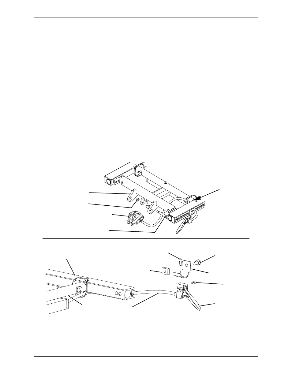
Mounting the Release Lever Assembly to the Seat
Frame
NOTE: For this procedure, refer to FIGURE 4.
NOTE: The release lever assembly consists of the release handle, cable and ratchet housing.
1. Insert the glide bearing into the ratchet housing.
2. Using the two 10‐32 X .69 pan head screws and #10 lock washers, secure the
cable/brake assembly to the ratchet housing. Torque to 32 in‐lbs.
3. Secure the ratchet housing to the mounting bracket on the center mount front rigging
support with the 5/16 X 1.625 inch socket head shoulder screw and 1/4‐20 inch locknut
provided (Detail “A”). Torque to 79 in‐lbs.
4. Secure the release handle to the release handle mounting bracket with the 10‐32 X .50
inch socket head screw and 10‐32 inch square nut. Securely tighten.
5. Secure the release handle mounting bracket to the T‐nut in the side rail with the
5/16‐18 X .50 inch hex head bolt. Torque to 13 ft‐lbs.
6. Tie‐wrap cable as shown in Detail “A”.
FIGURE 4 Mounting the Release Lever Assembly to the Seat Frame
5/16 X 1.625 inch Socket
Head Shoulder Screw
Ratchet Housing
1/4-20 inch Locknut
Center Mount Front
Rigging Support
NOTE: Seat pan not
shown for clarity.
DETAIL “A”
Seat Frame
10-32 inch
Square Nut
Release Handle
Release Handle
Mounting Bracket
Tie-Wrap the
Cable Here
10-32 X .50 inch
Socket Head Screw
T-Nut
(Shown exploded
for clarity)
Side Rail
Cable
5/16-18 X .50 inch
Hex Head Bolt