Impex IGS-06 User Manual
Page 7
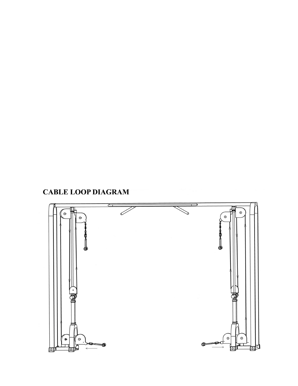
STEP 3 (See Diagram 3 & Cable Loop Diagram)
A.) Attach the horizontal beam on the Crossover Frame (#1) to the top of the two Guide
Rods (#12). Note: Help of a second or third person is a must!! Secure the Guide Rods
with two M10 x 1” Allen Bolts (#38) and
∅
¾” Washers (#32). Repeat the same
procedure to install the other side.
B.) Secure each end of Crossover Frame to each Rear Support Frame (#2) with one
Bracket (#16), two M12 x 4” Carriage Bolts (#28), two
∅
1” Washers (#29), and two
M12 Aircraft Nuts (#30).
C.) Attach an Upper Pulley Bracket (#9) to the horizontal beam on the Crossover Frame
(#1). Secure it with a M10 x 1” Allen Bolt (#38) and
∅
1 ½” Washer (#39). Repeat the
same step to install the other side.
D.) Attach the Cable (#20) to the Lower Pulley Bracket (#14). Attach a 6” Pulley (#18) to
the Bracket. Secure it with one M10 x 2” Allen Bolts (#31), two
∅
¾” Washers (#32),
and one M10 Aircraft Nut (#33).
E.) Pull the Cable (#20) to the open bracket on the Floor Stabilizer (#6). Repeat Step D
above to install a 6” Pulley (#18).
F.) Pull the Cable upward towards the open pulley bracket on the Crossover Frame (#1).
Install another 6” Pulley (#18).
G.) Draw the Cable downward to the Small Pulley Bracket (#8) on the Weight Holder (#4).
Install a 4 ½” Pulley (#19) to the bracket.
H.) Pull the Cable upward to the Upper Pulley Bracket (#9). Install a 6” Pulley.
I.) Repeat the steps above to install the other side.
J.) Attach a C-clip (#37) to the end of the Cable. Attach one end of a Chain (#36) to the C-
clip and the other end to the Handle. Repeat to install the other three handles.
6