Diagram 3 – Impex CG 1400 User Manual
Page 9
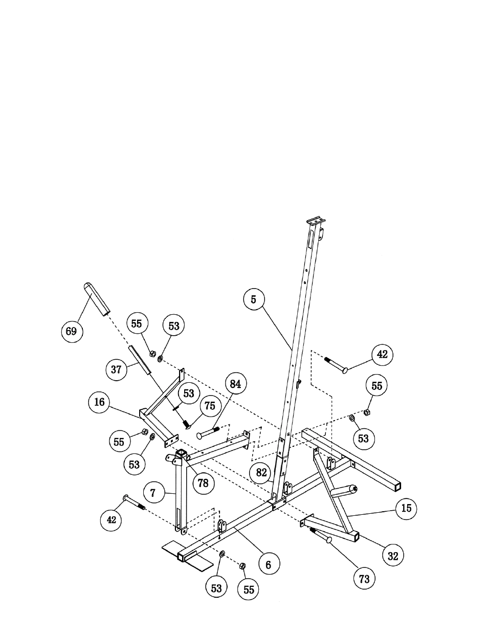
STEP 3 (See Diagram 3)
A.) Attach the Front Lower Vertical Beam (#82), both Left and Right Storage Frames
(#15)&(#16) to the Main Base Frame (#6). Secure them together with two M10 x 3” Carriage
Bolts (#73),
∅
¾” Washers (#53) and M10 Aircraft Nuts (#55). Do not tighten the nuts and
bolts yet.
B.) Secure the upper portion of Left & Right Storage Frames to the Front Vertical Beam (#5) with
one M10 x 2 ½” Carriage Bolt (#42),
∅
¾” Washer (#53), and M10 Aircraft Nut (#55).
C.) Attach the bottom of the Main Seat Support (#7) to the Main Base Frame (#6). Secure it with
one M10 x 2 ½” Carriage Bolt (#42),
∅
¾” Washer (#53), and M10 Aircraft Nut (#55).
D.) Attach the Main Seat Support (#7) to the Vertical Beams (#5). Secure it with two M10 x 2
3/4” Carriage Bolts (#84),
∅
¾” Washers (#53), and M10 Aircraft Nuts (#55).
E.) Attach two Storage Posts (#37) to the Left & Right Storage Frames. Secure each Storage
Post with one M10 x 1” Allen Bolt (#75) and Ø ¾” Washer (#53). Attach two Olympic Sleeves
(#69) to both Storage Posts.
F.) Securely tighten all nuts and bolts previously installed.
DIAGRAM
3
8