Impex MD-8850 User Manual
Marcy, Diamond elite, Olympic cage md-8850
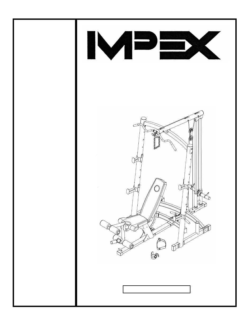
Table of contents
Document Outline
- BEFORE YOU BEGIN...................................................................................... 1
- IMPORTANT SAFETY NOTICES..................................................................... 2
- CAGE HARDWARE PACK……….....….............................................................4
- CAGE ASSEMBLY INSTRUCTIONS.................................................................6
- CAGE EXPLODED DIAGRAM.......................................................................…14
- CAGE PARTS LIST…………………………………………………………………. 15
- BENCH HARDWARE PACK……….....…..................................................…….16
- BENCH ASSEMBLY INSTRUCTIONS......................................................…….18
- BENCH EXPLODED DIAGRAM...............................................................……. 23
- BENCH PARTS LIST……………………………………………………………….. 24
- WARRANTY.................................................................................................… 25
- ORDERING PARTS......................................................................................... 25
- CAGE HARDWARE PACK
- CAGE ASSEMBLY INSTRUCTION
- Attach a Ø 2 ½” Rubber Bumper (#29) and the Weight Storage Post (#14) to Right Stabilizer (#3). Secure it with one M10 x ¾” Allen Bolt (#50) and Ø ¾” Washer (#52).
- Note: Do not tighten the Nuts and Bolts in following steps until instructed to do so.
- Connect the Right and Left Stabilizer (#2 & #3) by the Rear Base Frame (#4). Secure each end of the Rear Base Frame to each Stabilizer with four M10 x 2 3/8” Carriage Bolts (#43), one 4 ¾” x 3 ¼” Bracket (#17), four Ø ¾” Washers (#52), and four M10 Aircr
- Attach an Upright Beam (#1) onto the Right Stabilizer. Secure it with four M10 x 2 3/8” Carriage Bolts (#43), four Ø ¾” Washers (#52), and four M10 Aircraft Nuts (#54). Repeat the same step to install the other Upright Beam to the Left Stabilizer.
- Attach the Top Beam (#5) to the two Upright Beams. Secure each end of the Top Beam with one M10 x 4 1/8” Allen Bolt (#45) to the upper hole, one M10 x 4 1/8” Carriage Bolt (#40) to the lower hole, one 4” x 2 3/8” Curved Bracket (#16), two Ø ¾” Washers (#
- CAGE EXPLODED DIAGRAM
- CAGE PART LIST
- KEY NO. DESCRIPTION Q’ty
- BENCH PARTS LIST
- KEY NO. DESCRIPTION Q’ty