Rs-422 and rs-485 mode pinout – IBM CMX58886CX User Manual
Page 44
36
CMX58886CX cpuModule
BDM-610000050
Rev A
RS-422 and RS-485 Mode Pinout
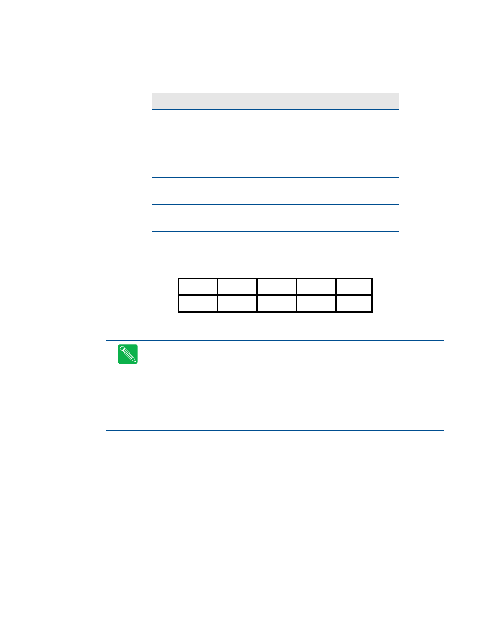
Table 21 provides the serial port connector pinout when RS-422 or RS-485 modes are enabled.
Facing the serial port connector, the pinout is:
Table 21
Serial Port in RS-422/485 Mode
Pin
Signal
Function
In/Out
DB-9
1
—
Data Carrier Detect
—
1
2
—
Data Set Ready
—
6
3
RXD–
Receive Data (–)
in
2
4
TXD+
Transmit Data (+)
out
7
5
TXD–
Transmit Data (–)
out
3
6
RXD+
Receive Data (+)
in
8
7
—
Reseved
—
4
8
—
Reseved
—
9
9,10
GND
Signal Ground
out
5
9
7
5
3
1
GND
Rsvd
TXD-
RXD-
Rsvd
GND
Rsvd
RXD+
TXD+
Rsvd
10
8
6
4
2
Note
When using the serial port in RS-485 mode, the serial transmitters are enabled and disabled under
software control. The transmitters are enabled by manipulating the Request To Send (RTS*) signal of the
serial port controller. This signal is controlled by writing bit 1 of the Modem Control Register (MCR) as
follows:
•
If MCR bit 1 = 1, then RTS* = 0, and serial transmitters are disabled
•
If MCR bit 1 = 0, then RTS* = 1, and serial transmitters are enabled
Note
For more information on the serial port registers, including the MCR, refer to the Serial Port
Programming reference on page 99.