Diagram 2 – Impex PHC 2000 User Manual
Page 7
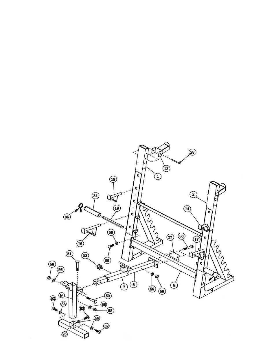
STEP 2 (See Diagram 2)
A.) Slide the Sliding Block (#7) onto the Main Seat Support (#6). Thread a M18 x
∅
3/8” Lock
Knob (#32) into the selected hole to hold the Sliding Block in position.
B.) Attach the Leg Developer Holder (#9) to the Front Stabilizer (#25). Secure it with three M10
x 5/8” Allen Bolts (#52) and
∅
¾” Washers (#56).
C.) Attach the Main Seat Support (#6) to the Leg Developer Holder. Secure it with one M10 x 2
½” Carriage Bolt (#51) from the top, two M10 x 2 ¾” Carriage Bolts (#50) from the side,
three
∅
¾” Washers (#56) and three M10 Aircraft Nuts (#58).
D.) Attach the Main Seat Support (#6) to the Cross Brace (#5). Secure it with two M10 x 2 ¾”
Carriage Bolts (#50), one 5 ½” x 2 ¾” Bracket (#27), two
∅
¾” Washers (#56), and two
M10 Aircraft Nuts (#58).
E.) Attach the two Squat Bar Catches (#13) to the back of the two Upright Beams. Secure
each Catch with a 5 ¾” L-shaped Pin (#28).
F.) Insert a Weight Post (#19) into the side hole on the Upright Beam. Secure it with one M10
x ¾” Allen Bolt (#59) and Ø ¾” Washer (#56). Slide an Olympic Sleeve (#34) onto the
Weight Post. Attach a Spring Clip (#35) to the Sleeve. Repeat for the other side.
G.) Insert the Right & Left Bar Catches (#14 &15), Right & Left Safety Catch (#16 &17) into the
selected holes on the Upright Beams (#1 & 2).
DIAGRAM 2
6