Diagram 2 – Impex PWR SURGE User Manual
Page 6
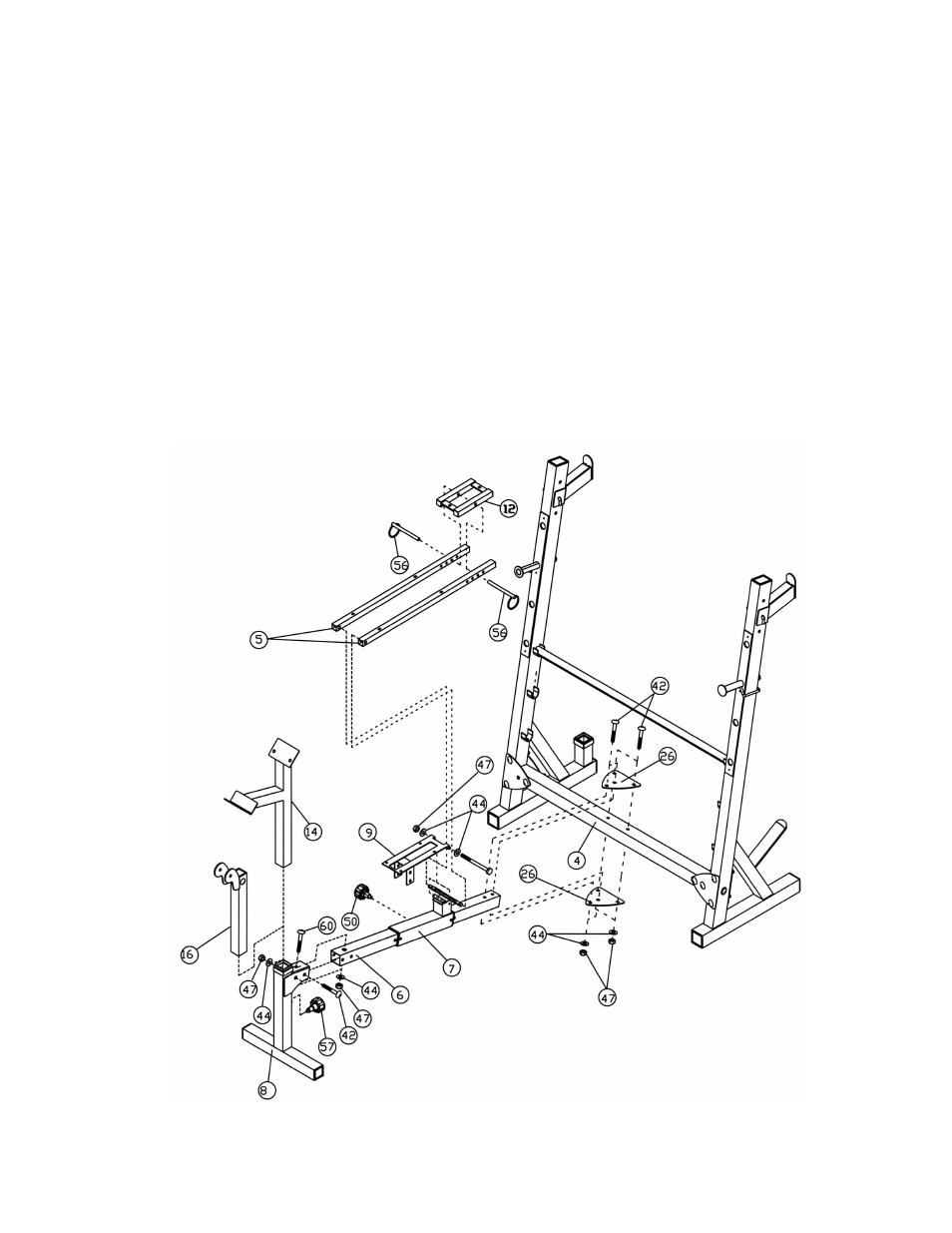
STEP 2 (See Diagram 2)
A.) Slide the Sliding Block (#7) onto the Main Seat Support (#6). Secure it with a
∅
3/8” Lock
Knob (#50) to a selected hole on the Main Seat Support.
B.) Attach the Front Stabilizer (#8) to the Main Seat Support (#6). Secure it with one M10 x 2
½” Carriage Bolt (#60), two M10 x 2 ¾” Carriage Bolts (#42),
∅
¾” Washers (#44), and
M10 Aircraft Nuts (#47).
C.) Attach the back of Main Seat Support (#6) to the Cross Brace (#4). Secure it with two
Brackets (#26), four M10 x 2 ¾” Carriage Bolts (#42),
∅
¾” Washers (#44), and M10
Aircraft Nuts (#47).
D.) Insert the Leg Developer Holder (#16) into the opening on the Front Stabilizer (#8). Secure
it with a
∅
½” Lock Knob (#57).
E.) Attach two Backrest Supports (#5) to the long pivot on the Sliding Block (#7). Place the
Headrest Bracket (#12) in between the two Backrest Supports (#5). Align the holes and
lock the desired Headrest position with a Lock Pin (#56).
F.) Attach the Seat Bracket (#9) to the short pivot on the Sliding Block (#7). Secure it with one
M10 x 4 ¾” Allen Bolt (#37), two
∅
¾” Washers (#44), and one M10 Aircraft Nut (#47).
DIAGRAM 2
5