Buccaneer gt, falcon gte, Assembly – IDEAL INDUSTRIES BUC5034 User Manual
Page 13
Buccaneer GT, Falcon GTE
- Installation, Assembly & Servicing
13
ASSEMBLY
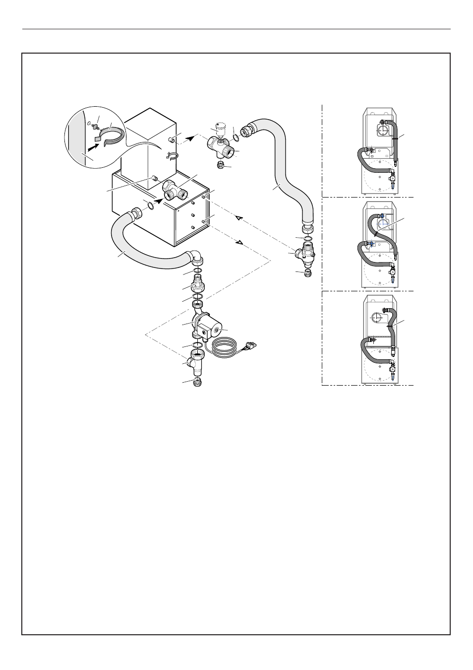
3.3 Hydraulic Boiler to Tank Connections Kit (BH46)
Connection kit BH46, provides connections from the tank to the
boiler.
The kit consists of
-
A pump with cable 3
-
Insulated flexible connector 13, length 1120mm
-
Insulated flexible connector with elbow 12, length 1200mm
-
A bag containing:
-
An antisyphon valve 10
-
Connecting union 4
-
Tee with union nut 1
-
Tee 7
-
Tee with tappings 9
-
3 X
1
/
2
" plugs 11
-
3 X 1
1
/
2
" O rings 5
-
5 X
3
/
4
" O rings 14
-
4 X plastic plugs 15
-
Flexible clip 16 with fixing 17
IMPORTANT
-
Ensure access to pump speed control and vent screw V
-
Ensure flexible connectors are run to prevent air pockets
-
The
1
/
2
" plug 11 fitted to Tee 1 can be replaced by a drain cock
-
To ensure best venting of the assembly and continued good
operation of the installation, an automatic vent (P) not supplied,
should be fitted on Tee 9 (
1
/
2
")
-
Screw the Tee with union nut 1 and plug 2 on tank outlet D
-
Fit the pump 3 to union nut 4 and Tee 1 inserting O rings 5
-
Screw Tee 7 to boiler return B
-
Screw Tee with tappings 9 with plug 11 to boiler flow A
-
Screw valve Tee 10 with plug 11 to tank inlet C
-
Connect elbow flexible 12 (1200mm) between 7 & 4 and flexible
13 (1120mm) between 9 & 10 inserting O rings 14.
-
Assemble flexible clip 16 and fitting 17 then clip them in the
7.5mm hole E on the boiler rear panel.
-
Fit flexible 13 in clip 16.
The pump cable allows simple connection to the boiler control
box. See Electrical section for further information.
(P)
(V)
1
11
3
4
7
14
10
14
14
11
11
A
C
D
B
9
5
5
14
12
13
E
E
E
Buccaneer
3 & 4
Buccaneer
5
Falcon
4 & 5
BUC5019
Lg= 1200 mm
Lg= 1180 mm
16
13
17
A.
B.
C.
D.
(P)
Boiler Flow 1
1
/
4
"
Boiler Return 1
1
/
4
"
Tank Inlet
3
/
4
"
Tank Outlet
3
/
4
"
Automatic Air Vent (not supplied)
Assembly