Installation, 3 connecting the protected equipment, Page 15 – MGE UPS Systems 1500 Tower User Manual
Page 15
Pb
Hertz 50/60 Hz
W/VA 1000W/1440VA
Ausg
Hertz 50/60 Hz
Amps 12A MAX
Netz
Util
Load
Mains
Reseau
Volt 120V~1O
Volt 120V~1O
36Vdc, 9Ah
U.S. PAT. NO. 6,094,363
Programmable
2
1
Vac OUT
I max 12A
U.P.S.
34Z5
R
Vac IN
SITE WIRING
FAULT
Data line protection
T20A/125V~
RS232
344-50254-00
IN
OUT
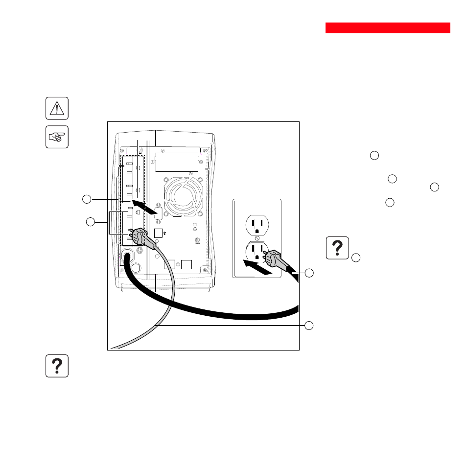
1 - Remove the power cord supplying the
equipment to be protected.
2 - Connect the power cord to the AC-power
wall receptacle 8 .
3 - Connect the protected equipment to the
UPS using the cord 20 . Connect critical
loads to the two standard receptacles 5 and
any non-critical loads to the two program-
mable receptacles 6 (1 and 2).
If the UPS is connected to a
computer running MGE communi-
cations software, it is possible to
program the interruption of power
to the programmable receptacles
6 during operation on battery
power, thus reserving backup
power for the critical loads.
4 - Lock the connections using the securing
system 26 (for rack models only).
3400723200/AC
- Page 15
2.3 Connecting the protected equipment
Check that the indications on the rating plate on the back of the UPS correspond to your AC-power system and to
the actual electrical consumption of all the equipment to be connected to the UPS.
2. Installation
8
As soon as the UPS is energized, the battery begins charging. Eight hours are required to charge to the full rated
backup time.
20
5
A Pulsar Evolution 1500 tower UPS has been used below to illustrate the instructions. The principle is the same for all the
other tower and rack models.
6
1
2