Setup, Network clock sync, Using the control panel – Momentum Sales & Marketing PRO CO MO8 User Manual
Page 14
14
Momentum mo8 Manual
Connection and Setup
Chapter 2
Setup
Network Clock Sync
PLEASE TAKE NOTE OF THE FOLLOWING:
The Momentum network MUST have ONE mi8 that is assigned CHANNEL 1. This assignment is
used to synchronize all of the device clocks on the network. Without this assignment, the system
clock will not sync and audio ‘clicks’ will be heard.
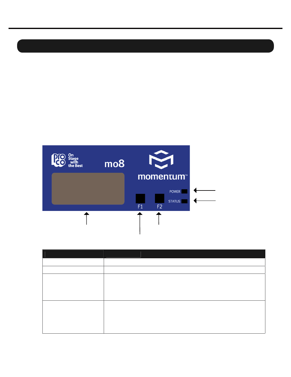
The mo8 unit includes a control panel with an LED display and two push buttons (F1 and F2).
The device can be confi gured through a series of key strokes using F1 and F2. The control panel
will only control the local device and cannot change other units via the network.
Using the Control Panel
F1 - Mode Edit / Decrease Value
F2 - Mode Select / Increase Value
Display
Status Indicator
Power Indicator
Button/LED
Description
F1 Mode Select:
F1 activates the edit mode within a particular function.
F2 Mode Select:
F2 generally selects which function to edit.
Power Indicator:
The power indicator shows that a power source is connected to the
Momentum units. The LED is connected to the digital power source.
All other power sources in the system can be monitored via the PC
software.
Status Indicator:
The status indicator is a bi-color LED. GREEN indicates all Momen-
tum Network connections have been found and the network is run-
ning. RED indicates there are one of two problems;
1) An Ethernet link is not established or is not connected.
2) The audio sync packet (channel 1) is not found.